pneumatic system diagram
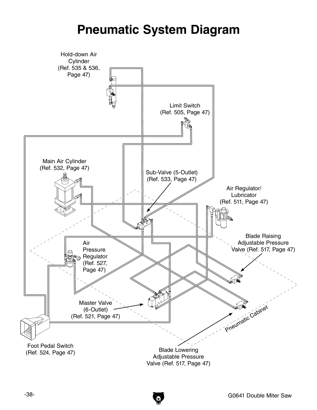
Pneumatic System Diagram
Cylinder
(Ref. 535 & 536,
Page 47)
Limit Switch
(Ref. 505, Page 47)
Main Air Cylinder |
|
(Ref. 532, Page 47) | |
| |
| (Ref. 533, Page 47) |
| Air Regulator/ |
| Lubricator |
| (Ref. 511, Page 47) |
� | � |
| Blade Raising |
Air | Adjustable Pressure |
Pressure | Valve (Ref. 517, Page 47) |
Regulator |
|
(Ref. 527, |
|
Page 47) |
|
Master Valve
(Ref. 521, Page 47)
Foot Pedal Switch
(Ref. 524, Page 47)Blade Lowering
Adjustable Pressure
Valve (Ref. 517, Page 47)
G0641 Double Miter Saw |