SECTION 7: SERVICE
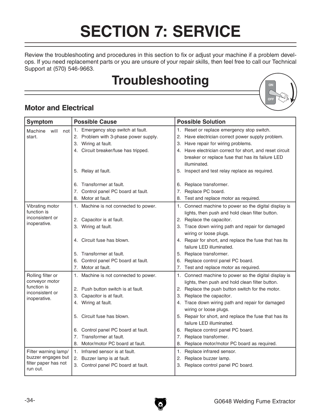
Review the troubleshooting and procedures in this section to fix or adjust your machine if a problem devel- ops. If you need replacement parts or you are unsure of your repair skills, then feel free to call our Technical Support at (570)
Troubleshooting
Motor and Electrical
Symptom | Possible Cause | Possible Solution | |||
Machine will not | 1. | Emergency stop switch at fault. | 1. | Reset or replace emergency stop switch. | |
start. | 2. | Problem with | 2. | Have electrician correct power supply problem. | |
| 3. | Wiring at fault. | 3. | Have repair for wiring problems. | |
| 4. | Circuit breaker/fuse has tripped. | 4. | Have electrician correct for short, and reset circuit | |
|
|
|
| breaker or replace fuse that has its failure LED | |
|
|
|
| illuminated. | |
| 5. | Relay at fault. | 5. | Inspect and test relay replace as required. | |
| 6. | Transformer at fault. | 6. | Replace transformer. | |
| 7. | Control panel PC board at fault. | 7. | Replace PC board. | |
| 8. | Motor at fault. | 8. | Test and replace motor as required. | |
|
|
|
|
| |
Vibrating motor | 1. | Machine is not connected to power. | 1. | Connect machine to power so the digital display is | |
function is |
|
|
| lights, then push and hold clean filter button. | |
inconsistent or | 2. | Capacitor is at fault. | 2. | Replace the capacitor. | |
inoperative. | |||||
3. | Wiring at fault. | 3. | Trace down wiring path and repair for damaged | ||
| |||||
|
|
|
| wiring or loose plugs. | |
| 4. | Circuit fuse has blown. | 4. | Repair for short, and replace the fuse that has its | |
|
|
|
| failure LED illuminated. | |
| 5. | Transformer at fault. | 5. | Replace transformer. | |
| 6. | Control panel PC board at fault. | 6. | Replace control panel PC board. | |
| 7. | Motor at fault. | 7. | Test and replace motor as required. | |
|
|
|
|
| |
Rolling filter or | 1. | Machine is not connected to power. | 1. | Connect machine to power so the digital display is | |
conveyor motor |
|
|
| lights, then push and hold clean filter button. | |
function is | 2. | Push button switch is at fault. | 2. | Replace the push button switch for the motor. | |
inconsistent or | |||||
3. | Capacitor is at fault. | 3. | Replace the capacitor. | ||
inoperative. | |||||
4. | Wiring at fault. | 4. | Trace down wiring path and repair for damaged | ||
| |||||
|
|
|
| wiring or loose plugs. | |
| 5. | Circuit fuse has blown. | 5. | Repair for short, and replace the fuse that has its | |
|
|
|
| failure LED illuminated. | |
| 6. | Control panel PC board at fault. | 6. | Replace control panel PC board. | |
| 7. | Transformer at fault. | 7. | Replace transformer. | |
| 8. | Motor/motor PC board at fault. | 8. | Replace motor/motor PC board as required. | |
|
|
|
|
| |
Filter warning lamp/ | 1. | Infrared sensor is at fault. | 1. | Replace infrared sensor. | |
buzzer engages but | 2. | Buzzer lamp is at fault. | 2. | Replace buzzer lamp. | |
filter paper has not | 3. | Control panel PC board at fault. | 3. | Replace control panel PC board. | |
run out. | |||||
|
|
|
| ||
|
|
|
|
| |
|
|
| G0648 Welding Fume Extractor | ||
