Setting Infeed Table
The infeed table height is set by calibrating the depth scale, and adjusting the positive stop bolts and depth stop lever.
Tools Needed | Qty |
Straightedge | 1 |
Phillips Head Screwdriver | 1 |
Wrench 14mm | 1 |
Hex Wrench 4mm | 1 |
Calibrating Depth Scale
The depth scale on the infeed table can be cali- brated or "zeroed" if it is not correct.
1.Set the outfeed table height as described in Setting Outfeed Table Height on Page 17.
2.Move the cutterhead guard out of the way.
3.Loosen the jam nut on the top height positive stop bolt (Figure 55) and raise the bolt so it does not obstruct the infeed table when it is raised in Step 5.
Top Height
Stop Bolt
Jam Nut
Bottom Height
Figure 55. Positive stop bolts for infeed table.
4.Place a straightedge across the infeed and outfeed tables.
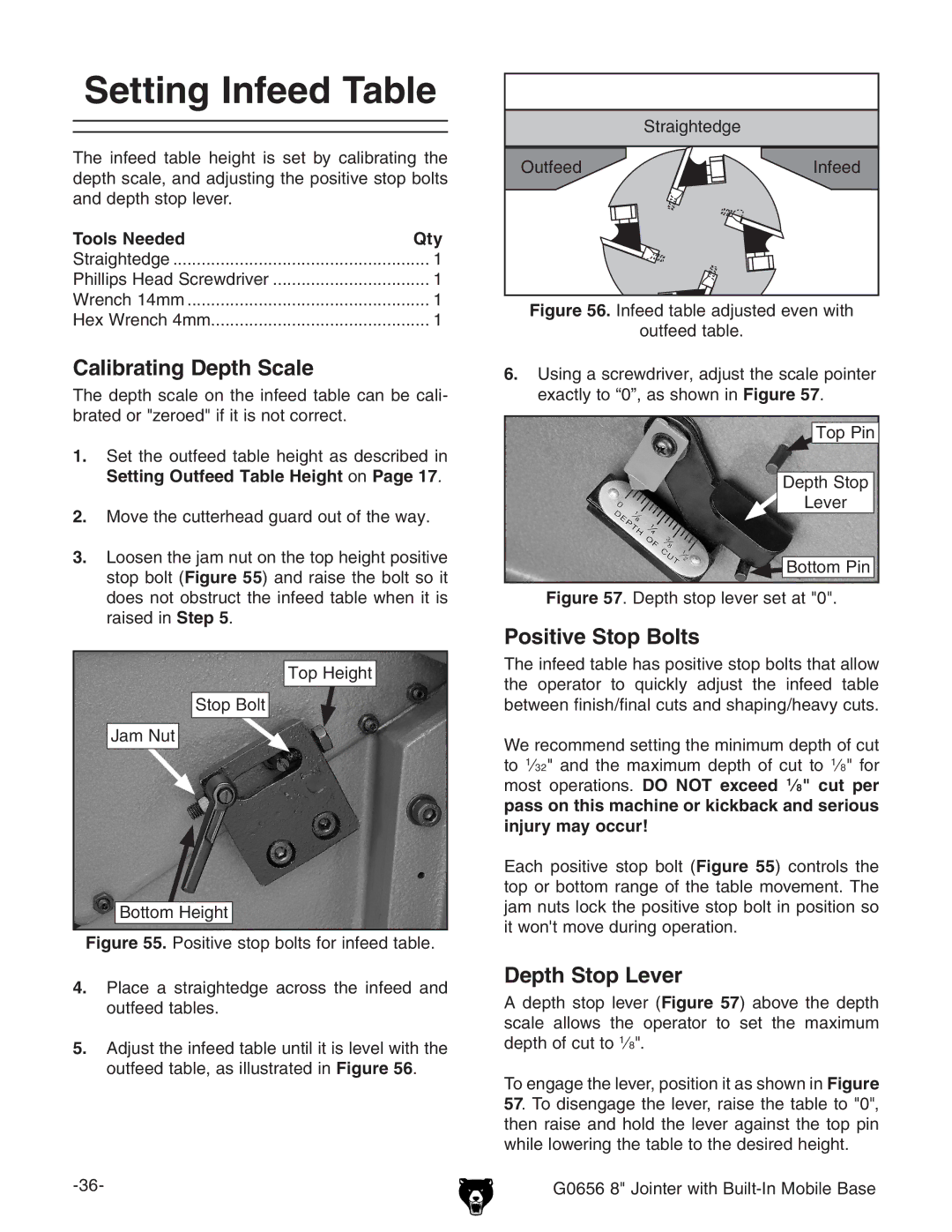
5.Adjust the infeed table until it is level with the outfeed table, as illustrated in Figure 56.
������������
������� ![]()
![]() ������
������
Figure 56. Infeed table adjusted even with
outfeed table.
6.Using a screwdriver, adjust the scale pointer exactly to “0”, as shown in Figure 57.
Top Pin
Depth Stop
Lever

 Bottom Pin
Figure 57. Depth stop lever set at "0".
Positive Stop Bolts
The infeed table has positive stop bolts that allow the operator to quickly adjust the infeed table between finish/final cuts and shaping/heavy cuts.
We recommend setting the minimum depth of cut to 1⁄32" and the maximum depth of cut to 1⁄8" for most operations. DO NOT exceed 1⁄8" cut per pass on this machine or kickback and serious injury may occur!
Each positive stop bolt (Figure 55) controls the top or bottom range of the table movement. The jam nuts lock the positive stop bolt in position so it won't move during operation.
Depth Stop Lever
Adepth stop lever (Figure 57) above the depth scale allows the operator to set the maximum depth of cut to 1⁄8".
To engage the lever, position it as shown in Figure 57. To disengage the lever, raise the table to "0", then raise and hold the lever against the top pin while lowering the table to the desired height.