Changing Belt
To remove the old belt:
1.DISCONNECT LATHE FROM POWER!
2.Release belt tension as described in
Changing Speed Ranges on Page 19, then remove the belt from the lower pulley.
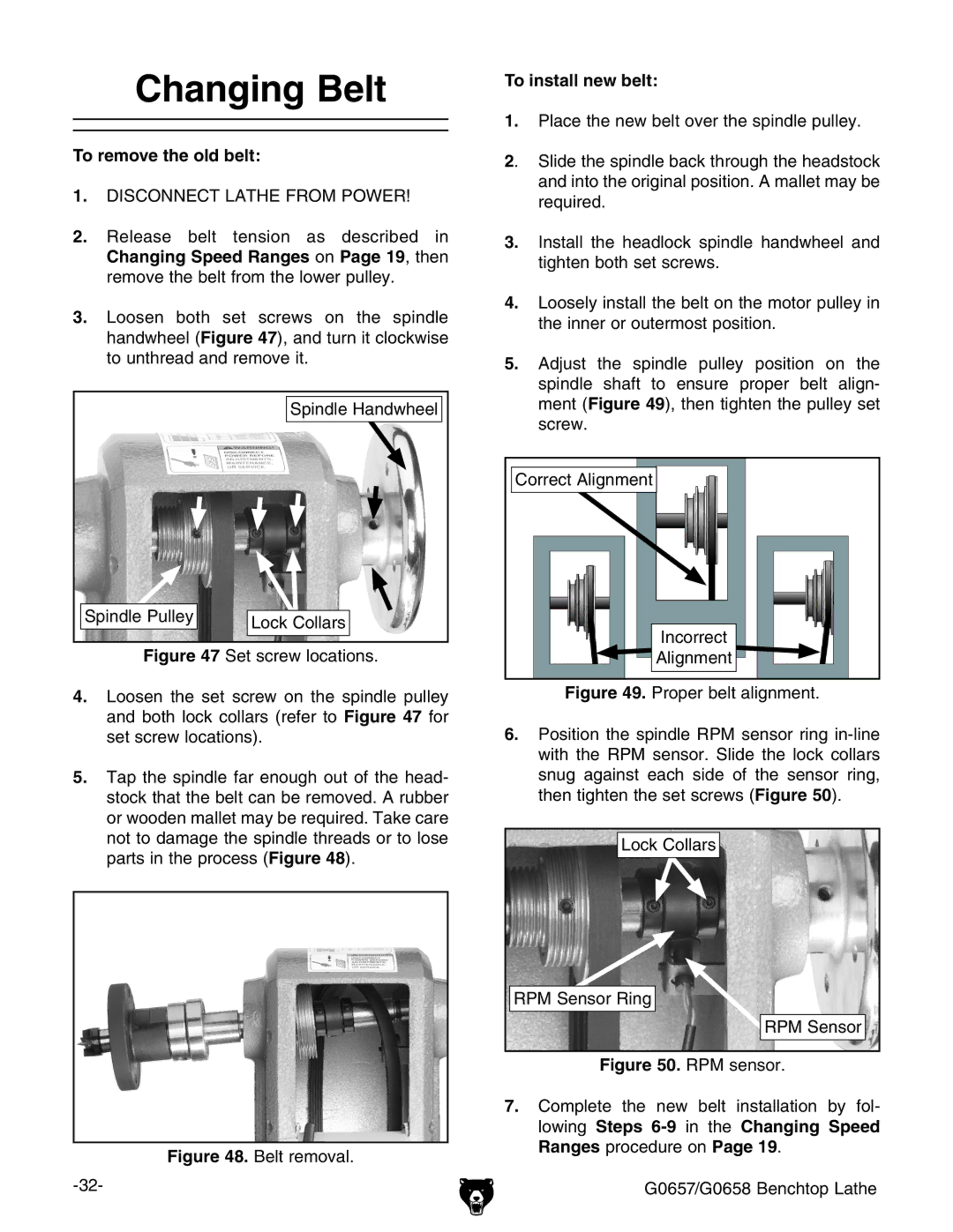
3.Loosen both set screws on the spindle handwheel (Figure 47), and turn it clockwise to unthread and remove it.
| Spindle Handwheel |
Spindle Pulley | Lock Collars |
|
Figure 47 Set screw locations.
4.Loosen the set screw on the spindle pulley and both lock collars (refer to Figure 47 for set screw locations).
5.Tap the spindle far enough out of the head- stock that the belt can be removed. A rubber or wooden mallet may be required. Take care not to damage the spindle threads or to lose parts in the process (Figure 48).
Figure 48. Belt removal.
To install new belt:
1.Place the new belt over the spindle pulley.
2. Slide the spindle back through the headstock and into the original position. A mallet may be required.
3.Install the headlock spindle handwheel and tighten both set screws.
4.Loosely install the belt on the motor pulley in the inner or outermost position.
5.Adjust the spindle pulley position on the spindle shaft to ensure proper belt align- ment (Figure 49), then tighten the pulley set screw.
Correct Alignment
Incorrect
![]() Alignment
Alignment![]()
Figure 49. Proper belt alignment.
6.Position the spindle RPM sensor ring in-line with the RPM sensor. Slide the lock collars snug against each side of the sensor ring, then tighten the set screws (Figure 50).
Lock Collars |
RPM Sensor Ring |
RPM Sensor |
Figure 50. RPM sensor.
7.Complete the new belt installation by fol- lowing Steps
G0657/G0658 Benchtop Lathe