NOTICE
This unit can be vented using only PVC (Class 160, ASTM
For water heaters in locations with high ambient temperatures (above 100° F) and/or insufficient dilution air, it is recommended that CPVC pipe and fittings (MUST USE SUPPLIED VENT TERMINAL) be used.
Horizontal Installation:
In a horizontal application, it is important that condensate not be allowed to buildup in the exhaust vent pipe. To prevent this from happening, the pipe should be installed with an slight upward slope. The vent system should be supported every 5 feet of vertical run and every 3 feet of horizontal run of vent pipe length.
Stress levels in the pipe and fittings can be significantly increased by improper installation. If rigid pipe clamps are used to hold the pipe in place, or if the pipe cannot move freely through a wall penetration, the pipe may be directly stressed, or high thermal stresses may be formed when the pipe heats up and expands. Install accordingly to minimize such stresses.
Follow the following procedure to vent through the wall:
1.Cut one 3 ½ in. (9.0 cm) diameter hole (for 3" (7.6 cm) diameter pipe) or 4 ½” (11.5 cm) diameter hole (for 4" (10.2 cm) diameter pipe).
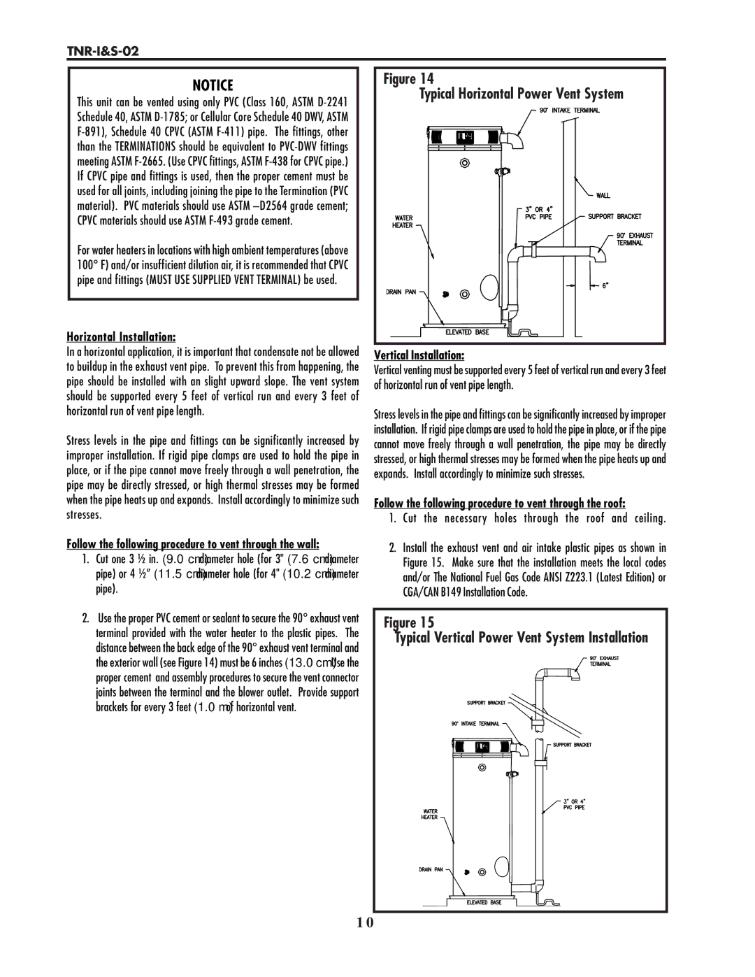
2.Use the proper PVC cement or sealant to secure the 90° exhaust vent terminal provided with the water heater to the plastic pipes. The distance between the back edge of the 90° exhaust vent terminal and the exterior wall (see Figure 14) must be 6 inches (13.0 cm). Use the proper cement and assembly procedures to secure the vent connector joints between the terminal and the blower outlet. Provide support brackets for every 3 feet (1.0 m) of horizontal vent.
Figure 14 |
Typical Horizontal Power Vent System |
Vertical Installation:
Vertical venting must be supported every 5 feet of vertical run and every 3 feet of horizontal run of vent pipe length.
Stress levels in the pipe and fittings can be significantly increased by improper installation. If rigid pipe clamps are used to hold the pipe in place, or if the pipe cannot move freely through a wall penetration, the pipe may be directly stressed, or high thermal stresses may be formed when the pipe heats up and expands. Install accordingly to minimize such stresses.
Follow the following procedure to vent through the roof:
1. Cut the necessary holes through the roof and ceiling.
2.Install the exhaust vent and air intake plastic pipes as shown in Figure 15. Make sure that the installation meets the local codes and/or The National Fuel Gas Code ANSI Z223.1 (Latest Edition) or CGA/CAN B149 Installation Code.
Figure 15
Typical Vertical Power Vent System Installation
1 0