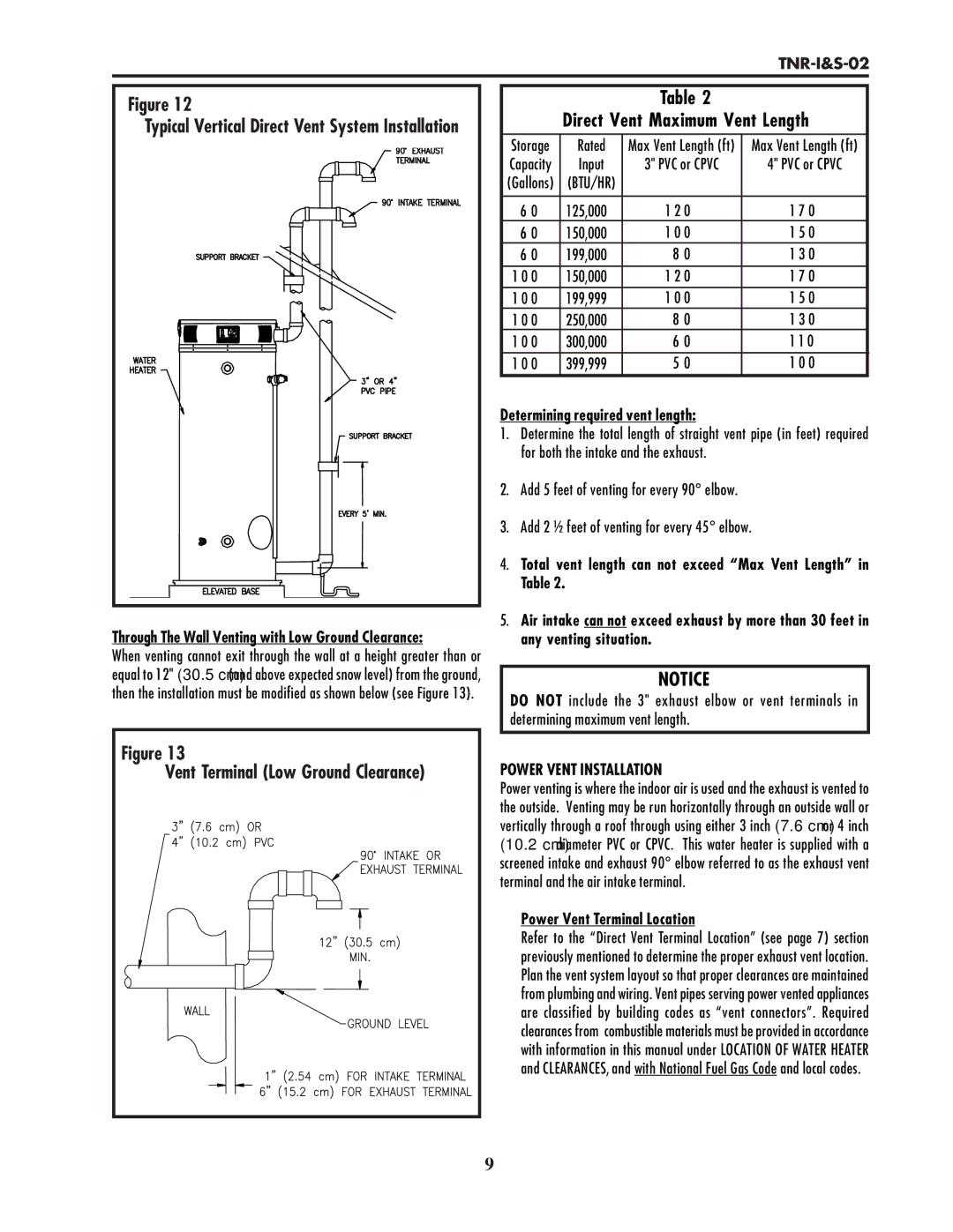
Figure 12 |
Typical Vertical Direct Vent System Installation |
Through The Wall Venting with Low Ground Clearance:
When venting cannot exit through the wall at a height greater than or equal to 12" (30.5 cm) (and above expected snow level) from the ground, then the installation must be modified as shown below (see Figure 13).
Figure 13 |
Vent Terminal (Low Ground Clearance) |
Table 2
Direct Vent Maximum Vent Length
Storage | Rated | Max Vent Length (ft) | Max Vent Length (ft) |
Capacity | Input | 3" PVC or CPVC | 4" PVC or CPVC |
(Gallons) | (BTU/HR) |
|
|
|
|
|
|
6 0 | 125,000 | 1 2 0 | 1 7 0 |
6 0 | 150,000 | 1 0 0 | 1 5 0 |
6 0 | 199,000 | 8 0 | 1 3 0 |
|
|
|
|
1 0 0 | 150,000 | 1 2 0 | 1 7 0 |
1 0 0 | 199,999 | 1 0 0 | 1 5 0 |
1 0 0 | 250,000 | 8 0 | 1 3 0 |
1 0 0 | 300,000 | 6 0 | 1 1 0 |
1 0 0 | 399,999 | 5 0 | 1 0 0 |
Determining required vent length:
1.Determine the total length of straight vent pipe (in feet) required for both the intake and the exhaust.
2.Add 5 feet of venting for every 90° elbow.
3.Add 2 ½ feet of venting for every 45° elbow.
4.Total vent length can not exceed “Max Vent Length” in Table 2.
5.Air intake can not exceed exhaust by more than 30 feet in any venting situation.
NOTICE
DO NOT include the 3" exhaust elbow or vent terminals in determining maximum vent length.
POWER VENT INSTALLATION
Power venting is where the indoor air is used and the exhaust is vented to the outside. Venting may be run horizontally through an outside wall or vertically through a roof through using either 3 inch (7.6 cm) or 4 inch (10.2 cm) diameter PVC or CPVC. This water heater is supplied with a screened intake and exhaust 90° elbow referred to as the exhaust vent terminal and the air intake terminal.
Power Vent Terminal Location
Refer to the “Direct Vent Terminal Location” (see page 7) section previously mentioned to determine the proper exhaust vent location. Plan the vent system layout so that proper clearances are maintained from plumbing and wiring. Vent pipes serving power vented appliances are classified by building codes as “vent connectors”. Required clearances from combustible materials must be provided in accordance with information in this manual under LOCATION OF WATER HEATER and CLEARANCES, and with National Fuel Gas Code and local codes.
9