| ||
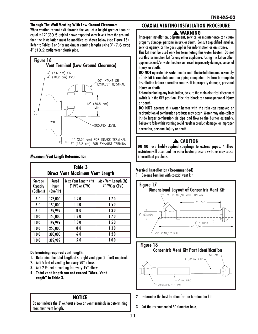
Through The Wall Venting With Low Ground Clearance: | COAXIAL VENTING INSTALLATION PROCEDURE | |
When venting cannot exit through the wall at a height greater than or | WARNING | |
equal to 12" (30.5 cm) (and above expected snow level) from the ground, | ||
Improper installation, adjustment, service, or maintenance can cause | ||
then the installation must be modified as shown below (see Figure 16). | ||
property damage, personal injury, or death. Consult a qualified installer, | ||
Refer to Tables 2 or 3 for maximum venting lengths using 3” (7.6 cm) or | ||
service agency, or the gas supplier for information or assistance. | ||
4” (10.2 cm) diameter plastic pipe. | ||
This kit must be used only for terminating this water heater. Do not | ||
| ||
Figure 16 | use this termination kit for any other appliance. Using this kit on other | |
appliances and/or water heaters can result in property damage, personal | ||
Vent Terminal (Low Ground Clearance) | ||
injury, or death. | ||
| ||
| DO NOT operate this water heater until the installation and assembly | |
| of this kit is complete and the piping completed. Failure to complete | |
| installation before operation can result in property damage, personal | |
| injury, or death. | |
| Before beginning any installation, be sure the main electrical disconnect | |
| switch is in the OFF position. Electrical shock can cause personal injury | |
| or death. | |
| DO NOT operate this water heater with the rain cap removed or | |
| recirculation of combustion products may occur. Water may also collect | |
| inside larger | |
| Failure to follow this warning could result in product damage, or improper | |
| operation, personal injury or death. | |
| CAUTION | |
| DO NOT use | |
Maximum Vent Length Determination | restriction will occur and the water heater pressure switches may cause | |
intermittent problems. |
Table 3
Direct Vent Maximum Vent Length
Storage | Rated | Max Vent Length (ft) | Max Vent Length (ft) |
Capacity | Input | 3" PVC or CPVC | 4" PVC or CPVC |
(Gallons) | (Btu/Hr) |
|
|
|
|
|
|
6 0 | 125,000 | 1 2 0 | 1 7 0 |
6 0 | 150,000 | 1 0 0 | 1 5 0 |
6 0 | 199,999 | 8 0 | 1 3 0 |
1 0 0 | 150,000 | 1 2 0 | 1 7 0 |
1 0 0 | 199,999 | 1 0 0 | 1 5 0 |
1 0 0 | 250,000 | 8 0 | 1 3 0 |
1 0 0 | 300,000 | 6 0 | 1 2 0 |
1 0 0 | 399,999 | 5 0 | 1 0 0 |
Determining required vent length:
1.Determine the total length of straight vent pipe (in feet) required.
2.Add 5 feet of venting for every 90° elbow.
3.Add 2 ½ feet of venting for every 45° elbow.
4.Total vent length can not exceed “Max. Vent ength” in Table 3.
NOTICE
Do not include the 3" exhaust elbow or vent terminals in determining maximum vent length.
Vertical Installation (Recommended) 1. Become familiar with coaxial vent kit.
Figure 17 |
Dimensional Layout of Concentric Vent Kit |
Figure 18 |
Concentric Vent Kit Part Identitication |
2.Determine the best location for the termination kit.
3.Cut the recommended 5" diameter hole.
1 1