AIR REQUIREMENTS
1.Do not obstruct the flow of combustion and ventilating air.
2.For safe operation, adequate air is needed for combustion and ventilation. Sooting may result in serious damage to the water heater and risk of fire or explosion. It can also create a risk of asphyxiation. Such a condition often will result in a yellow, luminous burner flame, causing carboning or sooting of the combustion chamber, burner and flue tubes.
MECHANICAL EXHAUSTING OF ROOM AIR
1.Where an exhaust fan is installed in the same room with this water heater and combustion air is drawn from inside the room, sufficient openings for air must be provided in the walls.UNDERSIZED OPENINGS WILL CAUSE AIR TO BE DRAWN INTO THE ROOM THROUGH THE WATER HEATER’S VENTING SYSTEM, CAUSING POOR COMBUSTION THAT MAY BE HAZARDOUS TO LIFE. SOOTING MAY RESULT IN SERIOUS DAMAGE TO THE WATER HEATER AND RISK OF FIRE OR EXPLOSION WHICH CAN ALSO CREATE A RISK OF ASPHYXIATION. Refer to local codes and /or National Fuel Gas Code for proper air opening sizing.
UNCONFINED SPACE
1.In buildings of conventional frame, brick or stone construction, unconfined spaces may provide adequate air for combustion and ventilation.
2.If the unconfined space is within a building of tight construction (buildings using the following construction: weather stripping, heavy insulation, caulking, vapor barrier, etc.), air for combustion and ventilation must be obtained from outdoors . This may be accomplished by piping air directly to the water heater from outside or providing opening or ducts in the wall. The installation instructions for confined spaces in tightly constructed buildings must be followed to ensure adequate air supply.
CONFINED SPACE
1.When drawing combustion air from inside a conventionally constructed building to a confined space, such a space shall be provided with two permanent openings.
•The top opening is to be located within twelve (12) inches of the enclosure top and the bottom opening within twelve (12) inches of the enclosure bottom.
•Each opening shall have a free area of at least one square inch per 1000 Btu/hr of the total input of all appliances in the enclosure, but not less than 100 square inches.
2.If the confined space is within a building of tight construction, air for combustion and ventilation must be obtained from outdoors. This may be accomplished by piping air directly to the water heater from outside or providing opening or ducts in the wall. When directly communicating with the outdoors through vertical ducts, two permanent openings, located in the above manner, shall be provided.
•Each opening shall have a free area of not less than one square inch per 4000 Btu/hr of the total input of all appliances in the enclosure.
•If horizontal ducts are used, each opening shall have a free area of not less than one square inch per 2000 Btu/hr of the total input of all appliances in the enclosure.
3.If the water heater is installed as a direct vent (outside air piped directly to the water heater), then additional opening, other than the opening for the air intake, are not required. However, adequate ventilation air must be provided in all cases to prevent increased room temperature.
CHEMICAL VAPOR CORROSION
Corrosion of the flue ways and vent system will occur if air for combustion contains certain chemical vapors. Such corrosion may result in poor combustion and create a risk of asphyxiation. Spray can propellants, cleaning solvents, refrigerator and air conditioning refrigerants, swimming pool chemicals, calcium and sodium chloride, waxes and process chemicals are corrosive. Products of this sort should not be stored near the water heater or outside by the air intake (if applicable).
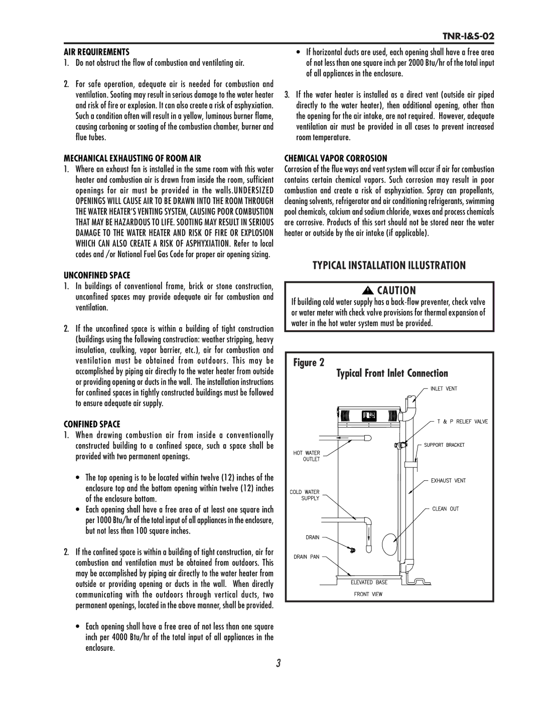
TYPICAL INSTALLATION ILLUSTRATION
![]()
![]() CAUTION
CAUTION
If building cold water supply has a
Figure 2 |
Typical Front Inlet Connection |
3