GAS CONNECTIONS
![]() WARNING
WARNING
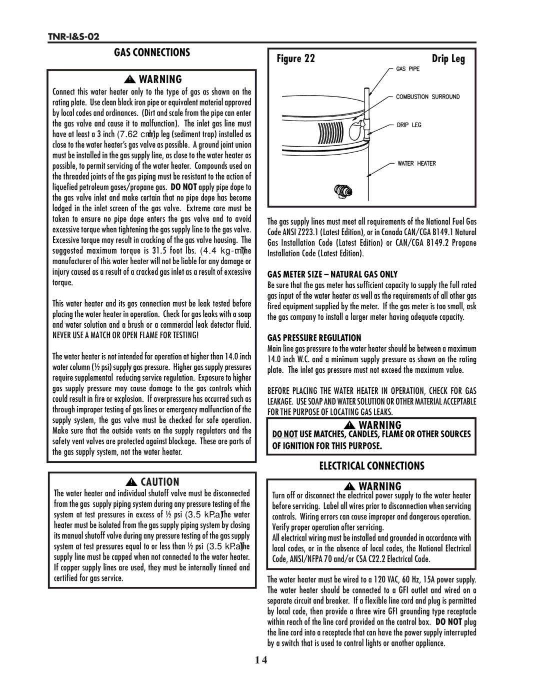
Connect this water heater only to the type of gas as shown on the rating plate. Use clean black iron pipe or equivalent material approved by local codes and ordinances. (Dirt and scale from the pipe can enter the gas valve and cause it to malfunction). The inlet gas line must have at least a 3 inch (7.62 cm) drip leg (sediment trap) installed as close to the water heater’s gas valve as possible. A ground joint union must be installed in the gas supply line, as close to the water heater as possible, to permit servicing of the water heater. Compounds used on the threaded joints of the gas piping must be resistant to the action of liquefied petroleum gases/propane gas. DO NOT apply pipe dope to the gas valve inlet and make certain that no pipe dope has become lodged in the inlet screen of the gas valve. Extreme care must be taken to ensure no pipe dope enters the gas valve and to avoid excessive torque when tightening the gas supply line to the gas valve. Excessive torque may result in cracking of the gas valve housing. The suggested maximum torque is 31.5 foot lbs. (4.4
This water heater and its gas connection must be leak tested before placing the water heater in operation. Check for gas leaks with a soap and water solution and a brush or a commercial leak detector fluid.
NEVER USE A MATCH OR OPEN FLAME FOR TESTING!
The water heater is not intended for operation at higher than 14.0 inch water column (½ psi) supply gas pressure. Higher gas supply pressures require supplemental reducing service regulation. Exposure to higher gas supply pressure may cause damage to the gas controls which could result in fire or explosion. If overpressure has occurred such as through improper testing of gas lines or emergency malfunction of the supply system, the gas valve must be checked for safe operation. Make sure that the outside vents on the supply regulators and the safety vent valves are protected against blockage. These are parts of the gas supply system, not the water heater.
![]()
![]() CAUTION
CAUTION
The water heater and individual shutoff valve must be disconnected from the gas supply piping system during any pressure testing of the system at test pressures in excess of ½ psi (3.5 kPa). The water heater must be isolated from the gas supply piping system by closing its manual shutoff valve during any pressure testing of the gas supply system at test pressures equal to or less than ½ psi (3.5 kPa). The supply line must be capped when not connected to the water heater. If copper supply lines are used, they must be internally tinned and certified for gas service.
Figure 22 | Drip Leg |
The gas supply lines must meet all requirements of the National Fuel Gas Code ANSI Z223.1 (Latest Edition), or in Canada CAN/CGA B149.1 Natural Gas Installation Code (Latest Edition) or CAN/CGA B149.2 Propane Installation Code (Latest Edition).
GAS METER SIZE – NATURAL GAS ONLY
Be sure that the gas meter has sufficient capacity to supply the full rated gas input of the water heater as well as the requirements of all other gas fired equipment supplied by the meter. If the gas meter is too small, ask the gas company to install a larger meter having adequate capacity.
GAS PRESSURE REGULATION
Main line gas pressure to the water heater should be between a maximum
14.0inch W.C. and a minimum supply pressure as shown on the rating plate. The inlet gas pressure must not exceed the maximum value.
BEFORE PLACING THE WATER HEATER IN OPERATION, CHECK FOR GAS LEAKAGE. USE SOAP AND WATER SOLUTION OR OTHER MATERIAL ACCEPTABLE FOR THE PURPOSE OF LOCATING GAS LEAKS.
![]()
![]() WARNING
WARNING
DO NOT USE MATCHES, CANDLES, FLAME OR OTHER SOURCES OF IGNITION FOR THIS PURPOSE.
ELECTRICAL CONNECTIONS
![]()
![]() WARNING
WARNING
Turn off or disconnect the electrical power supply to the water heater before servicing. Label all wires prior to disconnection when servicing controls. Wiring errors can cause improper and dangerous operation. Verify proper operation after servicing.
All electrical wiring must be installed and grounded in accordance with local codes, or in the absence of local codes, the National Electrical Code, ANSI/NFPA 70 and/or CSA C22.2 Electrical Code.
The water heater must be wired to a 120 VAC, 60 Hz, 15A power supply. The water heater should be connected to a GFI outlet and wired on a separate circuit and breaker. If a flexible line cord and plug is permitted by local code, then provide a three wire GFI grounding type receptacle within reach of the line cord provided on the control box. DO NOT plug the line cord into a receptacle that can have the power supply interrupted by a switch that is used to control lights or another appliance.
1 4