3.For horizontal, the venting system shall terminate 4 foot below, 4 foot horizontally from or 1 foot above any door, window, or gravity air inlet into building.
4.The manufacturer also recommends the vent system terminations not be installed closer than 3 feet from an inside corner of an L shaped structure.
5.The vent termination shall not be mounted directly above or within 3 feet horizontally from an oil tank vent or gas meter to avoid potential
6.The vent shall terminate a minimum of 12 inches above expected snowfall level to prevent blockage of vent termination.
Vent pipes serving power vented appliances are classified by building codes as “vent connectors”. Required clearances from combustible materials must be provided in accordance with information in this manual under LOCATION OF WATER HEATER and CLEARANCES, and with National Fuel Gas Code and local codes.
NOTICE
This unit can be vented using only PVC (Class 160, ASTM
For water heaters in locations with high ambient temperatures (above 100° F) and/or insufficient dilution air, it is recommended that CPVC pipe and fittings (MUST USE SUPPLIED VENT TERMINAL) be used.
Horizontal Installation:
In a horizontal application, it is important that condensate not be allowed to buildup in the exhaust vent pipe. To prevent this from happening the pipe should be installed with an slight upward slope so the condensate will run back toward the water heater. The vent system should be supported every 5 feet of vertical run and every 3 feet of horizontal run of vent pipe length.
Stress levels in the pipe and fittings can be significantly increased by improper installation. If rigid pipe clamps are used to hold the pipe in place, or if the pipe cannot move freely through a wall penetration, the pipe may be directly stressed, or high thermal stresses may be formed when the pipe heats up and expands. Install accordingly to minimize such stresses.
Follow the following procedure to vent through the wall:
1.Cut two 3 1/2 in. (8.9 cm) diameter holes (for 3" (7.6 cm) diameter pipe) or 4 ½” (11.4 cm) diameter holes (for 4" (10.2 cm) diameter pipe) in the wall with the centerline hole distances at least 18" (45.72 cm) apart in the location where the exhaust vent and air intake terminals will exit the outside wall if vented on the same wall.
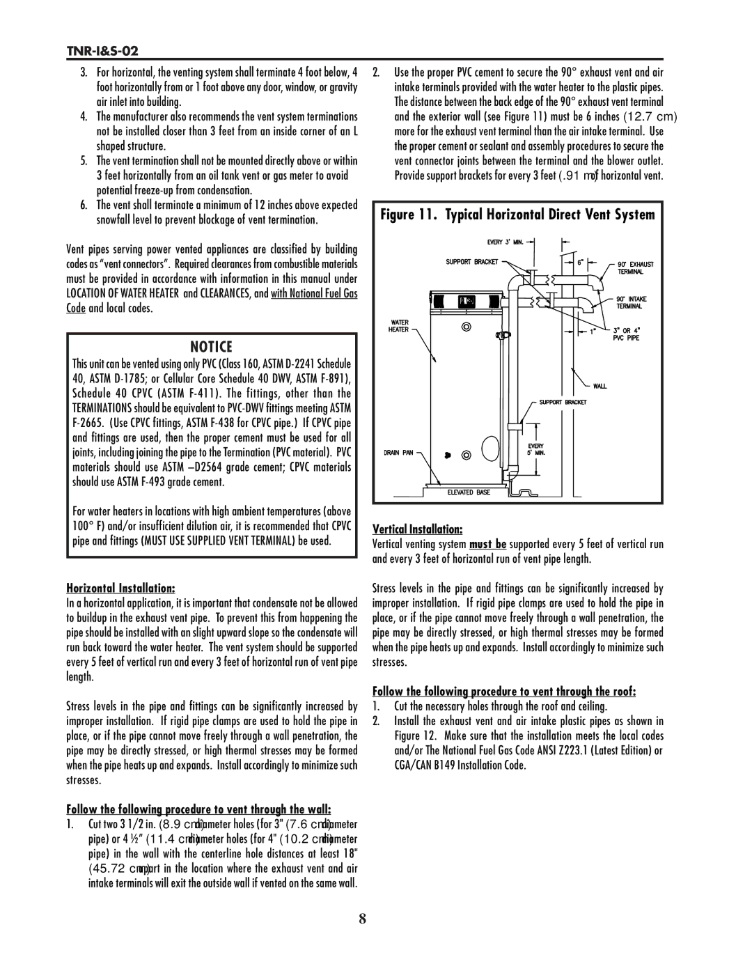
2.Use the proper PVC cement to secure the 90° exhaust vent and air intake terminals provided with the water heater to the plastic pipes. The distance between the back edge of the 90° exhaust vent terminal and the exterior wall (see Figure 11) must be 6 inches (12.7 cm) more for the exhaust vent terminal than the air intake terminal. Use the proper cement or sealant and assembly procedures to secure the vent connector joints between the terminal and the blower outlet. Provide support brackets for every 3 feet (.91 m) of horizontal vent.
Figure 11. Typical Horizontal Direct Vent System |
Vertical Installation:
Vertical venting system must be supported every 5 feet of vertical run and every 3 feet of horizontal run of vent pipe length.
Stress levels in the pipe and fittings can be significantly increased by improper installation. If rigid pipe clamps are used to hold the pipe in place, or if the pipe cannot move freely through a wall penetration, the pipe may be directly stressed, or high thermal stresses may be formed when the pipe heats up and expands. Install accordingly to minimize such stresses.
Follow the following procedure to vent through the roof:
1.Cut the necessary holes through the roof and ceiling.
2.Install the exhaust vent and air intake plastic pipes as shown in Figure 12. Make sure that the installation meets the local codes and/or The National Fuel Gas Code ANSI Z223.1 (Latest Edition) or CGA/CAN B149 Installation Code.
8