| |
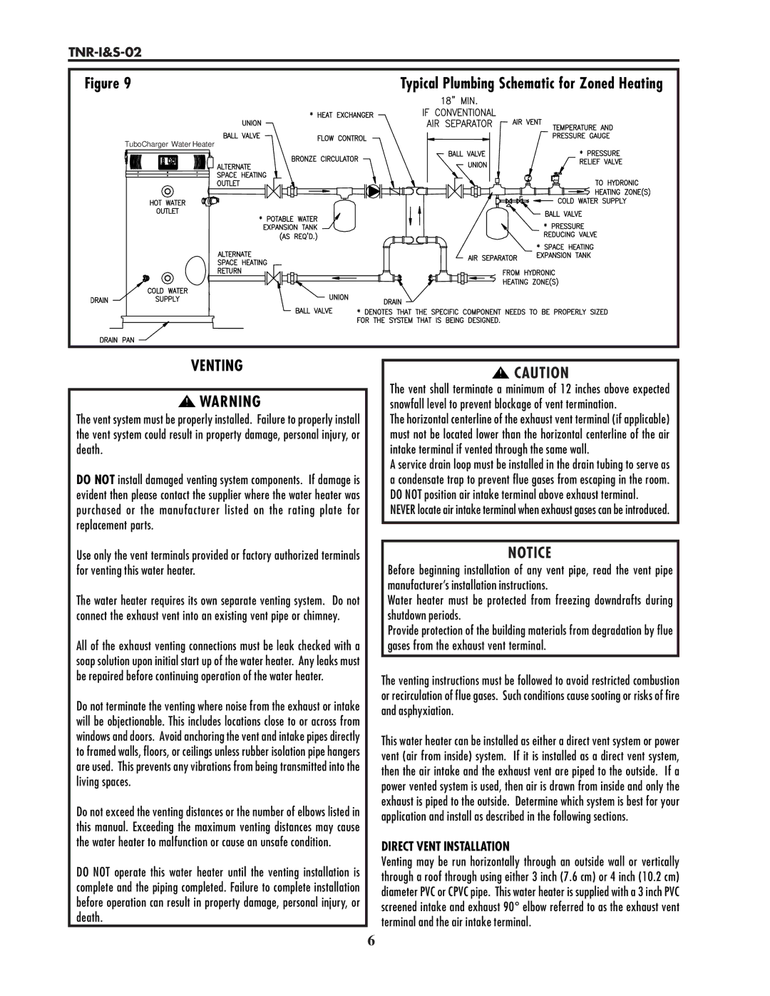
Figure 9 | Typical Plumbing Schematic for Zoned Heating |
TuboCharger Water Heater |
|
VENTING | CAUTION |
|
|
|
|
| The vent shall terminate a minimum of 12 inches above expected |
|
| WARNING |
| |
|
|
| snowfall level to prevent blockage of vent termination. | |
|
| |||
The vent system must be properly installed. Failure to properly install |
| The horizontal centerline of the exhaust vent terminal (if applicable) | ||
the vent system could result in property damage, personal injury, or |
| must not be located lower than the horizontal centerline of the air | ||
death. |
| intake terminal if vented through the same wall. | ||
DO NOT install damaged venting system components. If damage is |
| A service drain loop must be installed in the drain tubing to serve as | ||
| a condensate trap to prevent flue gases from escaping in the room. | |||
evident then please contact the supplier where the water heater was |
| DO NOT position air intake terminal above exhaust terminal. | ||
purchased or the manufacturer listed on the rating plate for |
| NEVER locate air intake terminal when exhaust gases can be introduced. | ||
replacement parts. |
|
| ||
| ||||
|
|
|
|
|
Use only the vent terminals provided or factory authorized terminals |
| NOTICE | ||
for venting this water heater. |
| Before beginning installation of any vent pipe, read the vent pipe | ||
|
|
|
| manufacturer’s installation instructions. |
The water heater requires its own separate venting system. Do not |
| Water heater must be protected from freezing downdrafts during | ||
connect the exhaust vent into an existing vent pipe or chimney. |
| shutdown periods. | ||
|
|
|
| Provide protection of the building materials from degradation by flue |
All of the exhaust venting connections must be leak checked with a |
| gases from the exhaust vent terminal. | ||
soap solution upon initial start up of the water heater. Any leaks must |
|
| ||
| ||||
be repaired before continuing operation of the water heater. |
| The venting instructions must be followed to avoid restricted combustion | ||
|
|
|
| |
Do not terminate the venting where noise from the exhaust or intake |
| or recirculation of flue gases. Such conditions cause sooting or risks of fire | ||
| and asphyxiation. | |||
will be objectionable. This includes locations close to or across from |
| |||
|
| |||
windows and doors. Avoid anchoring the vent and intake pipes directly |
| This water heater can be installed as either a direct vent system or power | ||
to framed walls, floors, or ceilings unless rubber isolation pipe hangers |
| |||
| vent (air from inside) system. If it is installed as a direct vent system, | |||
are used. This prevents any vibrations from being transmitted into the |
| |||
| then the air intake and the exhaust vent are piped to the outside. If a | |||
living spaces. |
| |||
| power vented system is used, then air is drawn from inside and only the | |||
|
|
|
| |
Do not exceed the venting distances or the number of elbows listed in |
| exhaust is piped to the outside. Determine which system is best for your | ||
| application and install as described in the following sections. | |||
this manual. Exceeding the maximum venting distances may cause |
| |||
|
| |||
the water heater to malfunction or cause an unsafe condition. |
| DIRECT VENT INSTALLATION | ||
|
|
|
| |
DO NOT operate this water heater until the venting installation is |
| Venting may be run horizontally through an outside wall or vertically | ||
| through a roof through using either 3 inch (7.6 cm) or 4 inch (10.2 cm) | |||
complete and the piping completed. Failure to complete installation |
| |||
| diameter PVC or CPVC pipe. This water heater is supplied with a 3 inch PVC | |||
before operation can result in property damage, personal injury, or |
| |||
| screened intake and exhaust 90° elbow referred to as the exhaust vent | |||
death. |
| |||
| terminal and the air intake terminal. | |||
6