Air System
Various functions on the Model G9983 are con- trolled through the air system. Since this is a com- plex network of hoses and valves, please take some time to familiarize yourself with each item so you can better understand your machine dur- ing adjustments.
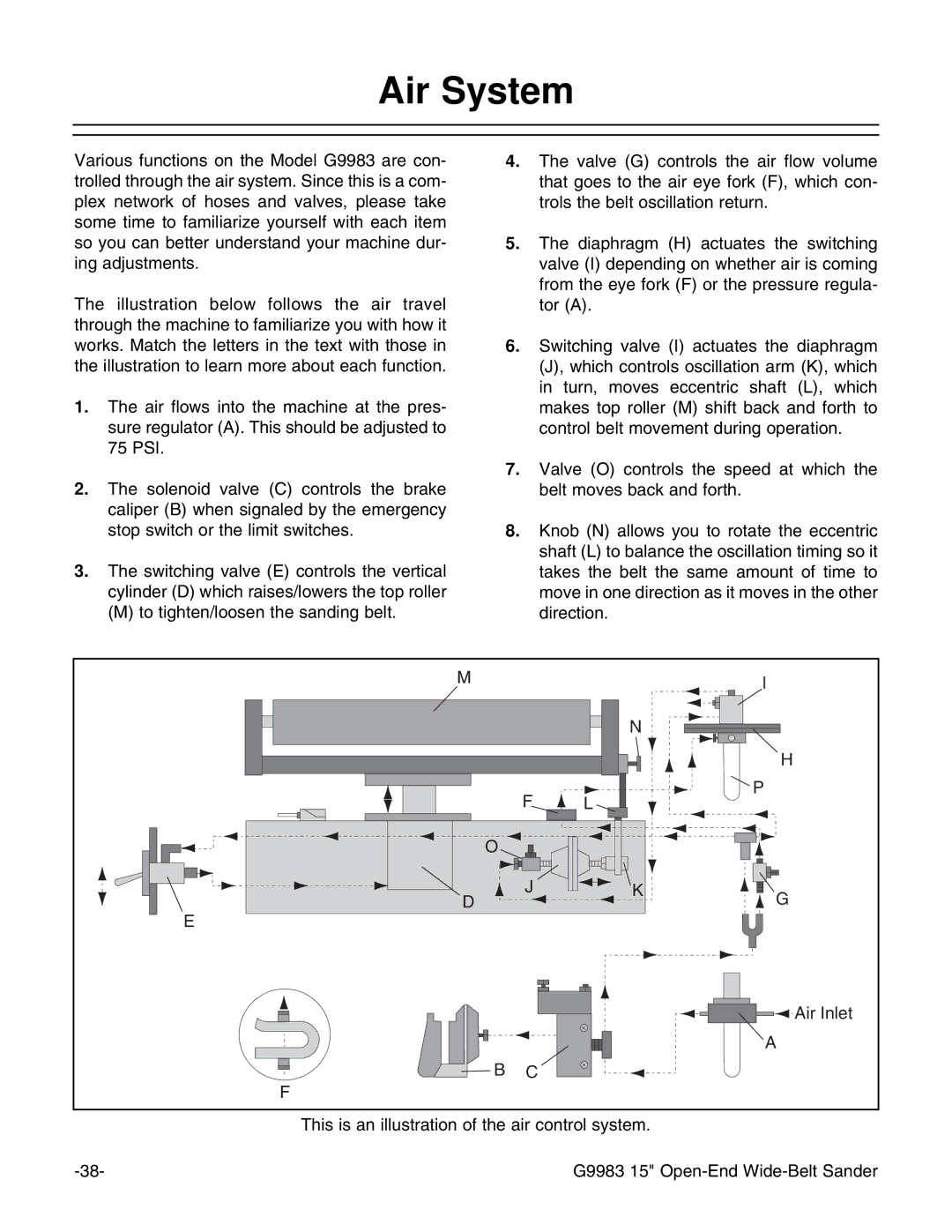
The illustration below follows the air travel through the machine to familiarize you with how it works. Match the letters in the text with those in the illustration to learn more about each function.
1.The air flows into the machine at the pres- sure regulator (A). This should be adjusted to 75 PSI.
2.The solenoid valve (C) controls the brake caliper (B) when signaled by the emergency stop switch or the limit switches.
3.The switching valve (E) controls the vertical cylinder (D) which raises/lowers the top roller
(M) to tighten/loosen the sanding belt.
4.The valve (G) controls the air flow volume that goes to the air eye fork (F), which con- trols the belt oscillation return.
5.The diaphragm (H) actuates the switching valve (I) depending on whether air is coming from the eye fork (F) or the pressure regula- tor (A).
6.Switching valve (I) actuates the diaphragm (J), which controls oscillation arm (K), which in turn, moves eccentric shaft (L), which makes top roller (M) shift back and forth to control belt movement during operation.
7.Valve (O) controls the speed at which the belt moves back and forth.
8.Knob (N) allows you to rotate the eccentric shaft (L) to balance the oscillation timing so it takes the belt the same amount of time to move in one direction as it moves in the other direction.
M
N
F L
O
I
H
P
D
E
J ![]()
![]() K
K
G
B | C |
F
Air Inlet
A
This is an illustration of the air control system.
G9983 15" |