CONNECTION AND PREPARATION _______
R TV
|
|
|
| AUX IN |
|
PTICAL | AM EXT | FM EXT | L | R | SUB WOOFER |
IGITAL |
|
|
|
| OUT PUT |
UT PUT |
|
|
|
|
|
| AM | COAXIAL | L | R |
|
| LOOP | 75Ω |
| LINE OUT |
|
|
| ANTENNA |
|
|
|
MIN. 4 Ω |
|
IMPEDANCE | L |
| |
SPEAKERS | L |
|
|
|
|
| AUX IN |
|
OPTICAL | AM EXT | FM EXT | L | R | SUB WOOFER |
DIGITAL |
|
|
|
| OUT PUT |
OUT PUT |
|
|
|
|
|
| AM | COAXIAL | L | R |
|
| LOOP | 75Ω |
| LINE OUT |
|
|
| ANTENNA |
|
| |
|
|
|
|
|
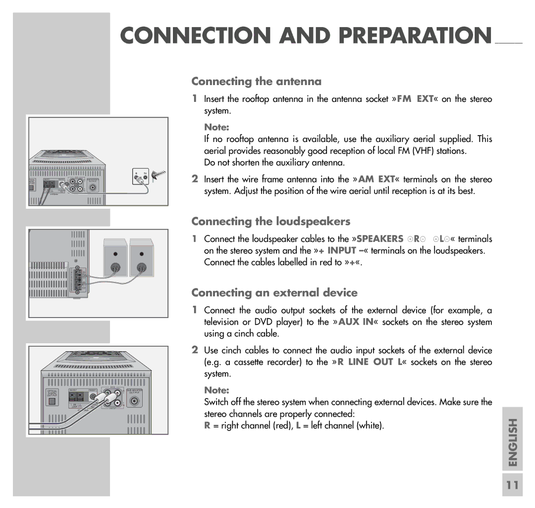
Connecting the antenna
1Insert the rooftop antenna in the antenna socket »FM EXT« on the stereo system.
Note:
If no rooftop antenna is available, use the auxiliary aerial supplied. This aerial provides reasonably good reception of local FM (VHF) stations.
Do not shorten the auxiliary antenna.
2Insert the wire frame antenna into the » AM EXT« terminals on the stereo system. Adjust the position of the wire aerial until reception is at its best.
Connecting the loudspeakers
1Connect the loudspeaker cables to the »SPEAKERS xRy xLy« terminals on the stereo system and the »+ INPUT
Connecting an external device
1 Connect the audio output sockets of the external device (for example, a television or DVD player) to the » AUX IN« sockets on the stereo system using a cinch cable.
2 Use cinch cables to connect the audio input sockets of the external device (e.g. a cassette recorder) to the » R LINE OUT L« sockets on the stereo
system. |
| |
Note: |
| |
Switch off the stereo system when connecting external devices. Make sure the |
| |
stereo channels are properly connected: | ENGLISH | |
R = right channel (red), L = left channel (white). | ||
|
11
