OVERVIEW__________________________________________________________________________________
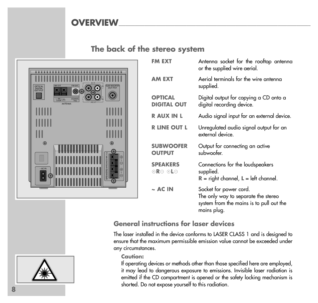
The back of the stereo system
OPTICAL
DIGITAL
OUT PUT
˜AC IN
|
|
| AUX IN |
|
AM EXT | FM EXT | L | R | SUB WOOFER |
|
|
|
| OUT PUT |
AM | COAXIAL | L | R |
|
LOOP | 75Ω |
| ||
| LINE OUT |
| ||
| ANTENNA |
|
| |
|
|
|
|
MIN. 4 Ω | L | |
IMPEDANCE | ||
| ||
SPEAKERS | L | |
|
FM EXT | Antenna socket for the rooftop antenna |
| or the supplied wire aerial. |
AM EXT | Aerial terminals for the wire antenna |
| supplied. |
OPTICAL | Digital output for copying a CD onto a |
DIGITAL OUT | digital recording device. |
R AUX IN L | Audio signal input for an external device. |
R LINE OUT L | Unregulated audio signal output for an |
| external device. |
SUBWOOFER | Output for connecting an active |
OUTPUT | subwoofer. |
SPEAKERS | Connections for the loudspeakers |
xRy xLy | supplied. |
| R = right channel, L = left channel. |
~ AC IN | Socket for power cord. |
| The only way to separate the stereo |
| system from the mains is to pull out the |
| mains plug. |
General instructions for laser devices
The laser installed in the device conforms to LASER CLASS 1 and is designed to ensure that the maximum permissible emission value cannot be exceeded under any circumstances.
Caution:
If operating devices or methods other than those specified here are employed, it may lead to dangerous exposure to emissions. Invisible laser radiation is emitted if the CD compartment is opened or the safety locking mechanism is shorted. Do not expose yourself to this radiation.
8
