Installation
The heating mode may be one of the following options:
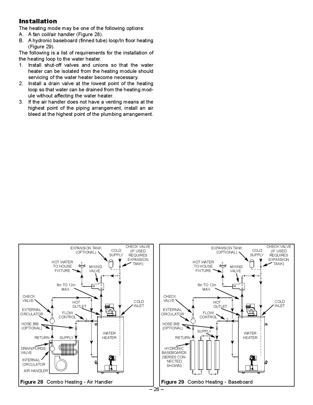
A.A fan coil/air handler (Figure 28).
B.A hydronic baseboard (finned tube) loop/In floor heating (Figure 29).
The following is a list of requirements for the installation of the heating loop to the water heater.
1.Install
2.Install a drain valve at the lowest point of the heating loop so that water can be drained from the heating mod- ule without affecting the water heater.
3.If the air handler does not have a venting means at the highest point of the piping arrangement, install an air bleed at the highest point of the plumbing arrangement.
|
| EXPANSION TANK | COLD | CHECK VALVE |
|
|
| EXPANSION TANK | COLD | CHECK VALVE | ||||||||
|
| (IF USED |
|
|
| (IF USED | ||||||||||||
|
|
| (OPTIONAL) |
|
|
|
|
| (OPTIONAL) |
| ||||||||
|
|
|
| SUPPLY | REQUIRES |
|
|
|
|
| SUPPLY | REQUIRES | ||||||
|
|
|
|
|
|
|
|
|
|
|
|
| ||||||
| HOT WATER |
|
|
|
| EXPANSION |
|
| HOT WATER |
|
|
|
| EXPANSION | ||||
|
|
|
|
| TANK) |
|
|
|
|
|
| TANK) | ||||||
| TO HOUSE | MIXING |
|
|
|
| TO HOUSE | MIXING |
|
| ||||||||
|
|
|
|
|
|
|
|
| ||||||||||
| FIXTURE | VALVE |
|
|
|
|
|
| FIXTURE | VALVE |
|
|
|
| ||||
|
| 8in TO 12in |
| M | C |
|
|
|
|
|
| 8in TO 12in |
| M | C |
|
|
|
|
| MAX. |
|
| H |
|
|
|
|
|
| MAX. |
|
| H |
|
|
|
|
|
|
|
|
|
|
|
|
|
|
|
|
|
|
|
| ||
CHECK |
|
|
|
|
|
|
|
|
| CHECK |
|
|
|
|
|
|
|
|
VALVE |
| HOT |
|
|
|
| COLD |
| VALVE |
| HOT |
|
|
|
| COLD | ||
EXTERNAL |
| OUTLET |
|
|
|
| INLET |
| EXTERNAL |
| OUTLET |
|
|
|
| INLET | ||
| FLOW |
|
|
|
|
|
|
| FLOW |
|
|
|
|
| ||||
CIRCULATOR |
|
|
|
|
|
|
| CIRCULATOR |
|
|
|
|
|
| ||||
|
| CONTROL |
|
|
|
|
|
|
|
| CONTROL |
|
|
|
|
| ||
HOSE BIB |
|
|
|
|
|
|
|
|
| HOSE BIB |
|
|
|
|
|
|
|
|
(OPTIONAL) |
|
|
|
|
|
|
|
|
| (OPTIONAL) | SUPPLY |
|
|
|
|
| ||
|
| SUPPLY |
|
| WATER |
|
|
|
|
|
| WATER |
|
| ||||
|
|
|
|
|
|
|
|
|
|
|
|
|
|
| ||||
RETURN |
|
| HEATER |
|
|
| RETURN |
| HEATER |
|
| |||||||
DRAIN/PURGE |
|
|
|
|
|
|
|
|
| HYDRONIC |
|
|
|
|
|
|
|
|
VALVE |
|
|
|
|
|
|
|
|
| BASEBOARDS |
|
|
|
|
|
|
|
|
INTERNAL |
|
|
|
|
|
|
|
|
| (SERIES CON- |
|
|
|
|
|
|
|
|
|
|
|
|
|
|
|
|
| NECTED |
|
|
|
|
|
|
|
| |
CIRCULATOR |
|
|
|
|
|
|
|
|
|
|
|
|
|
|
|
|
| |
|
|
|
|
|
|
|
|
| SHOWN) |
|
|
|
|
|
|
|
| |
|
|
|
|
|
|
|
|
|
|
|
|
|
|
|
|
|
| |
AIR HANDLER |
|
|
|
|
|
|
|
|
|
|
|
|
|
|
|
|
|
|
Figure 28 Combo Heating - Air Handler |
|
| Figure 29 | Combo Heating - Baseboard |
| |||||||||||||
|
|
|
|
|
|
|
|
|
|
|
|
|
|
|
|
|
|
|
– 26 –