|
|
|
|
|
|
|
|
|
|
|
|
|
| DO NOT use any lead based solder in potable water lines. | |||||
|
| FOLLOW THE |
|
|
|
|
| ||||||||||||
|
| TEMPERING |
|
|
|
|
|
|
|
| Use appropriate | ||||||||
|
|
|
|
|
|
| TEMPERED |
| |||||||||||
|
| VALVE MANU- |
|
|
|
|
|
|
| WATER TO |
|
| DO NOT tamper with the gas control/thermostat, igniter, | ||||||
|
| ||||||||||||||||||
|
| FACTURER'S |
|
|
|
|
|
|
| FIXTURE |
|
| |||||||
| INSTRUCTIONS |
|
|
|
|
|
|
|
|
|
| flammable vapour sensor or temperature and pressure | |||||||
|
|
|
|
| |||||||||||||||
|
|
|
|
|
|
|
|
|
|
|
|
|
|
|
|
| relief valve. Tampering voids all warranties. Only qualified | ||
|
|
|
|
|
|
|
|
|
|
|
|
|
|
|
|
| service technicians should service these components. | ||
|
|
|
|
|
|
|
|
|
|
| DO NOT use with piping that has been treated with chro- | ||||||||
|
| T&P VALVE |
|
|
|
|
| ||||||||||||
|
| AND DIS- |
|
|
|
|
|
|
|
|
| mates, boiler seal, or other chemicals. | |||||||
|
|
|
|
|
|
|
| ||||||||||||
|
| CHARGE |
|
|
|
|
|
|
|
|
|
|
|
|
|
| |||
|
|
|
|
|
|
| TEMPERING |
|
| DO NOT add any chemicals to the system piping which will | |||||||||
|
| LINE |
|
|
|
|
|
|
| ||||||||||
|
|
|
|
|
|
|
|
|
|
|
|
| VALVE (SET |
|
| contaminate the potable water supply. | |||
|
|
|
|
|
|
|
|
|
|
|
|
|
|
| |||||
|
|
|
|
|
|
|
|
|
|
|
|
| TO 49°C |
|
| ||||
|
|
|
|
|
|
|
| HOT | |||||||||||
|
|
|
|
|
|
|
|
|
|
| |||||||||
|
|
|
|
|
|
|
| WATER |
|
| (120°F)) |
|
| Closed System/Thermal Expansion | |||||
|
|
|
|
|
|
|
| OUTLET |
|
|
|
|
|
| |||||
|
|
|
|
|
|
|
|
|
|
|
|
|
|
|
| ||||
|
|
|
| COLD |
|
|
|
|
|
| Periodic discharge of the temperature and pressure relief | ||||||||
|
|
|
|
|
|
|
|
|
| valve may be due to thermal expansion in a closed water | |||||||||
|
|
|
| WATER |
|
|
|
|
|
| |||||||||
|
|
|
| INLET |
|
|
|
|
|
| supply system. The water utility supply meter may contain a | ||||||||
|
|
|
|
|
|
|
|
|
|
|
|
|
|
|
|
| check valve, backflow preventer or water | ||
|
|
|
|
|
|
|
|
|
|
|
|
|
|
|
|
| valve. This will create a closed water system. During the | ||
|
|
|
|
|
|
|
|
|
|
|
|
|
|
|
|
| heating cycle of the water heater, the water expands caus- | ||
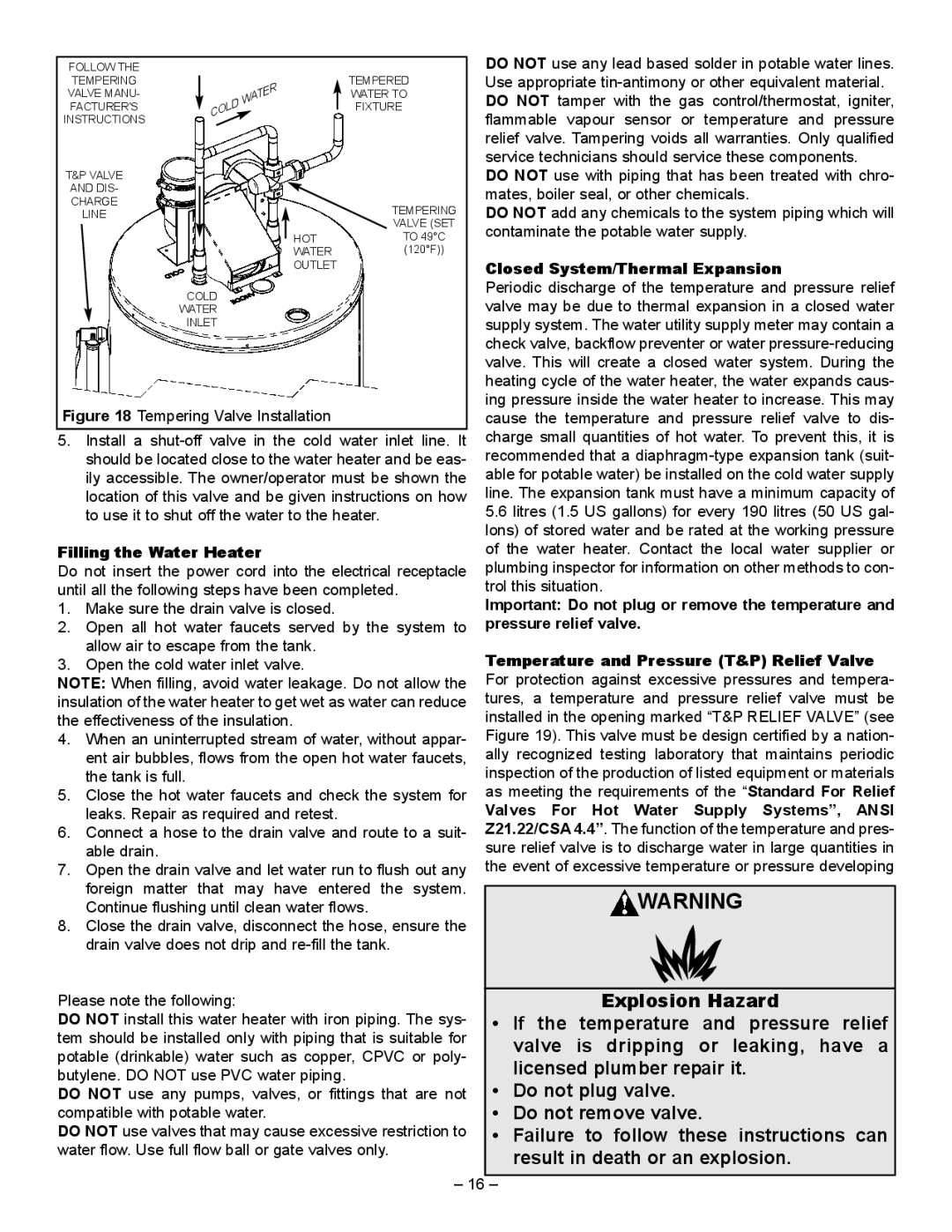
| Figure 18 Tempering Valve Installation |
|
|
|
|
|
| ing pressure inside the water heater to increase. This may | |||||||||||
|
|
|
|
|
|
| cause the temperature and pressure relief valve to dis- | ||||||||||||
5. Install a |
| charge small quantities of hot water. To prevent this, it is | |||||||||||||||||
|
| should be located close to the water heater and be eas- |
| recommended that a | |||||||||||||||
|
| ily accessible. The owner/operator must be shown the |
| able for potable water) be installed on the cold water supply | |||||||||||||||
|
| location of this valve and be given instructions on how |
| line. The expansion tank must have a minimum capacity of | |||||||||||||||
|
| to use it to shut off the water to the heater. |
| 5.6 litres (1.5 US gallons) for every 190 litres (50 US gal- | |||||||||||||||
|
|
|
|
|
|
|
|
|
|
|
|
|
|
|
|
| lons) of stored water and be rated at the working pressure | ||
Filling the Water Heater |
|
|
|
|
|
| of the water heater. Contact the local water supplier or | ||||||||||||
Do not insert the power cord into the electrical receptacle |
| plumbing inspector for information on other methods to con- | |||||||||||||||||
until all the following steps have been completed. |
| trol this situation. | |||||||||||||||||
1. Make sure the drain valve is closed. |
|
|
|
|
|
| Important: Do not plug or remove the temperature and | ||||||||||||
2. Open all hot water faucets served by the system to |
| pressure relief valve. | |||||||||||||||||
|
| allow air to escape from the tank. |
|
|
|
|
|
| Temperature and Pressure (T&P) Relief Valve | ||||||||||
3. Open the cold water inlet valve. |
|
|
|
|
|
| |||||||||||||
NOTE: When filling, avoid water leakage. Do not allow the |
| For protection against excessive pressures and tempera- | |||||||||||||||||
insulation of the water heater to get wet as water can reduce |
| tures, a temperature and pressure relief valve must be | |||||||||||||||||
the effectiveness of the insulation. |
|
|
|
|
|
| installed in the opening marked “T&P RELIEF VALVE” (see | ||||||||||||
4. When an uninterrupted stream of water, without appar- |
| Figure 19). This valve must be design certified by a nation- | |||||||||||||||||
|
| ent air bubbles, flows from the open hot water faucets, |
| ally recognized testing laboratory that maintains periodic | |||||||||||||||
|
| the tank is full. |
|
|
|
|
|
| inspection of the production of listed equipment or materials | ||||||||||
5. Close the hot water faucets and check the system for |
| as meeting the requirements of the “Standard For Relief | |||||||||||||||||
|
| leaks. Repair as required and retest. |
|
|
|
|
|
| Valves For Hot Water Supply Systems”, ANSI | ||||||||||
6. Connect a hose to the drain valve and route to a suit- |
| Z21.22/CSA 4.4”. The function of the temperature and pres- | |||||||||||||||||
|
| able drain. |
|
|
|
|
|
| sure relief valve is to discharge water in large quantities in | ||||||||||
7. Open the drain valve and let water run to flush out any |
| the event of excessive temperature or pressure developing | |||||||||||||||||
|
| foreign matter that may have entered the system. |
|
|
|
| |||||||||||||
|
|
|
|
| WARNING | ||||||||||||||
|
| Continue flushing until clean water flows. |
|
|
| ||||||||||||||
8.Close the drain valve, disconnect the hose, ensure the drain valve does not drip and
Please note the following: |
|
| Explosion Hazard | |
DO NOT install this water heater with iron piping. The sys- | • | If the | temperature | and pressure relief |
tem should be installed only with piping that is suitable for |
| valve | is dripping | or leaking, have a |
potable (drinkable) water such as copper, CPVC or poly- |
| |||
| licensed plumber repair it. | |||
butylene. DO NOT use PVC water piping. | • | |||
DO NOT use any pumps, valves, or fittings that are not | Do not plug valve. |
| ||
compatible with potable water. | • | Do not remove valve. | ||
DO NOT use valves that may cause excessive restriction to | • | Failure | to follow these instructions can | |
water flow. Use full flow ball or gate valves only. |
| result in death or an explosion. | ||
|
| |||
– 16 |
|
|
|
|
– |
|
|
| |