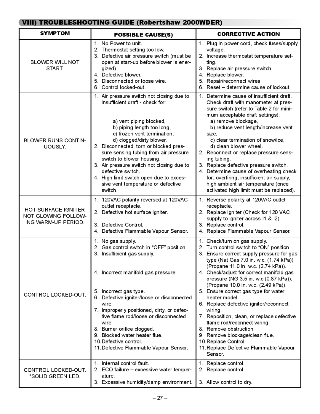
VIII) TROUBLESHOOTING GUIDE (Robertshaw 2000WDER)
SYMPTOM |
| POSSIBLE CAUSE(S) |
| CORRECTIVE ACTION | |
|
|
|
|
| |
| 1. | No Power to unit. | 1. | Plug in power cord, check fuses/supply | |
| 2. | Thermostat setting too low. |
| voltage. | |
| 3. | Defective air pressure switch (must be | 2. | Increase thermostat temperature set- | |
BLOWER WILL NOT |
| open at |
| ting. | |
START. |
| gized). | 3. | Replace air pressure switch. | |
| 4. | Defective blower. | 4. | Replace blower. | |
| 5. | Disconnected or loose wire. | 5. | Repair/reconnect wires. | |
| 6. | Control | 6. | Reset – determine cause of lockout. | |
|
|
|
|
| |
| 1. | Air pressure switch not closing due to | 1. | Determine cause of insufficient draft. | |
|
| insufficient draft - check for: |
| Check draft with manometer at pres- | |
|
|
|
| sure switch (refer to Table 2 for mini- | |
|
|
|
| mum acceptable draft settings). | |
|
| a) vent piping blocked, |
| a) remove blockage, | |
|
| b) piping length too long, |
| b) reduce vent length/increase vent | |
|
| c) frozen vent termination, |
| size, | |
BLOWER RUNS CONTIN- |
| d) clogged/dirty blower. |
| c) clear termination of snow/ice, | |
UOUSLY. | 2. | Disconnected, torn or blocked pres- |
| d) clean blower wheel. | |
|
| sure sensing tubing from air pressure | 2. | Reconnect or replace pressure sens- | |
|
| switch to blower housing. |
| ing tubing. | |
| 3. | Air pressure switch not closing due to | 3. | Replace defective pressure switch. | |
|
| defective switch. | 4. | Determine cause of overheating check | |
| 4. | High limit switch open due to exces- |
| for: overfiring, insufficient air supply, | |
|
| sive vent temperature or defective |
| high ambient air temperature (once | |
|
| switch. |
| activated high limit must be replaced). | |
|
|
|
|
| |
| 1. | 120VAC polarity reversed at 120VAC | 1. | Reverse polarity at 120VAC outlet | |
HOT SURFACE IGNITER |
| outlet receptacle. |
| receptacle. | |
2. | Defective hot surface igniter. | 2. | Replace igniter (Check for 120 VAC | ||
NOT GLOWING FOLLOW- | |||||
|
|
| supply to igniter across I1 & I2). | ||
ING |
|
|
| ||
3. | Defective Control. | 3. | Replace control. | ||
| |||||
| 4. | Defective Flammable Vapour Sensor. | 4. | Replace Flammable Vapour Sensor. | |
|
|
|
|
| |
| 1. | No gas supply. | 1. | Check/turn on gas supply. | |
| 2. | Gas control switch in “OFF” position. | 2. | Turn control switch to “ON” position. | |
| 3. | Insufficient gas supply. | 3. | Ensure correct supply pressure for gas | |
|
|
|
| type (Nat Gas 7.0 in. w.c. (1.74 kPa)) | |
| 4. | Incorrect manifold gas pressure. |
| (Propane 11.0 in. w.c. (2.74 kPa)). | |
| 4. | Check/adjust for correct manifold gas | |||
|
|
|
| pressure (NG 3.5 in. w.c.(0.87 kPa)), | |
| 5. | Incorrect gas type. |
| (Propane 10.0 in. w.c. (2.49 kPa)). | |
CONTROL | 5. | Ensure correct gas type for water | |||
6. | Defective igniter/loose or disconnected |
| heater model. | ||
|
| ||||
|
| wire. | 6. | Replace defective igniter/reconnect | |
| 7. | Improperly positioned, dirty, or defec- |
| wiring. | |
|
| tive flame rod/loose or disconnected | 7. | Reposition, clean, or replace defective | |
|
| wire. |
| flame rod/reconnect wiring. | |
| 8. | Burner orifice clogged. | 8. | Remove obstruction. | |
| 9. | Blocked water heater flue. | 9 | Remove blockage/clean flue. | |
| 10.Defective control. | 10.Replace Control. | |||
| 11. Defective Flammable Vapour Sensor. | 11. Replace Defective Flammable Vapour | |||
|
|
|
| Sensor. | |
|
|
|
|
| |
| 1. | Internal control fault. | 1. | Replace control. | |
CONTROL | 2. | ECO failure – excessive water temper- | 2. | Replace control. | |
*SOLID GREEN LED. |
| ature. |
|
| |
| 3. | Excessive humidity/damp environment. | 3. | Allow control to dry. | |
|
|
|
|
| |
– 27 –
