Diagnostic Repair Manual
Diagnostic Repair Manual
Electrical Formulas
Fuel Consumption
Engine
Stator Winding Resistance Values / Rotor Resistance
Mounting Dimensions
Specifications
Major Features
Part General Information
Item Number
Introduction
Serial Number
Grounding the Generator
Transfer Switch / Load Center
Prepackaged Transfer Switches
Selecting a Location
Prepackaged Installation Basics Part
System Control Interconnections
Power Source and Load Lines
Fuel Requirements
General
Measuring AC Voltage
Visual Inspection
Meters
VOM
Measuring Current
Measuring AC Frequency
Measuring Resistance
Volt
Electrical Units
Ohms LAW
Ampere
Megohmmeter
Insulation Resistance
Stator Insulation Resistance Test
Test Between Windings
Testing ALL Stator Windings to Ground
Rotor Insulation Resistance Test
Cleaning the Generator
Drying the Generator
Overcrank Shutdown
High OIL Temperature Shutdown
LOW OIL Pressure Shutdown
Overspeed Shutdown
Auto position
Control Panel
OFF Position
Manual Position
Protection Systems
SET Exercise Switch
To Select Automatic Operation
Manual Transfer to Standby Manual Startup
Manual Shutdown and Retransfer Back to Utility
Automatic Operating Sequences
Automatic Operating Parameters
SEQ. Condition Action SENSOR, Timer or Other
Part AC Generators
AC Generator
Rotor Assembly
ENGINE-GENERATOR Drive System
Excitation Circuit Breaker
Stator Assembly
Brush Holder and Brushes
Other AC Generator Components
Main Line Circuit Breaker
Voltage Regulator
Field Boost
Rotor Residual Magnetism
Field Boost Circuit
Operation
Troubleshooting Flowcharts
Troubleshooting Flowcharts Part
Section
Section
Discussion
Safety
Procedure
Test 1- Check Main Circuit Breaker
Test 3- Test Excitation Circuit Breaker
Test 2- Check AC Output Voltage
If a high voltage is indicated, go on to Test
Set VOM to AC volts
Test 4- Fixed Excitation Test Rotor AMP Draw Test
Test 6 Check Field Boost
Test 5 Wire Continuity
Test 7 Testing the Stator with a VOM
Set VOM to the Rx1 scale
Test 8 Resistance Check Rotor Circuit
Test 9 Check Brushes Slip Rings
Remove wire 4 from the voltage regulator
If continuity was measured in steps 5 and 6 proceed to step
Start the engine, let it stabilize and warm up at no-load
Test 10 Test Rotor Assembly
Test 12 Check and Adjust Engine Governor
Test 11 Check AC Output Frequency
Loosen the governor clamp bolt Figure
Procedure 7KW Units
Test 16 Check Engine Condition
Test 13 Check and Adjust Voltage Regulator
Test 15 Check for Overload Condition
Test 14 Check Voltage Frequency Under Load
Part Type Prepackaged Transfer Switches
Enclosure
Standby Closing Coil C2
Limit Switches XA1 and XB1
Transfer Mechanism
Utility Closing Coil C1
Terminal Block
Transfer Relay
Neutral LUG
Manual Transfer Handle
Fuses F1, F2
Fuse Holder
Utility 1
Terminals 23
Operational Analysis
Wiring Diagram and Schematic
Utility Source Voltage Available
Utility Source Power Available
Utility Source Voltage Failure
Generator Power Available, Waiting to Transfer
Transfer Action to Standby Position
Transfer to Standby
Generator Powering Load
Utility Restored, Generator Still Providing Output to Load
Utility Restored
Utility Restored, Transfer Relay De-energized
Utility RESTORED, Transfer Switch DE-ENERGIZED
Utility RESTORED, Retransfer Back to Utility
Transfer Switch in Utility
Transfer Switch in Utility
Introduction to Troubleshooting
Troubleshooting Flow Charts Part
If the generator has been shut down, proceed as follows
Test 21- Check Voltage AT Terminal Lugs E1, E2
Test 22 Check Voltage AT Standby Closing Coil C2
Continuity Results
Test 24- Check Manual Transfer Switch Operation
Test 23 Test Transfer Relay TR
Now, connect the VOM test leads across Relay Terminals 1
Test 25- Test Limit Switch XB1
PROCEDURE/RESULTS
WIRING/CONNECTIONS
Test 27- Check Voltage AT Terminal Lugs N1, N2
Test 29- Check Voltage AT Utility Closing Coil C1
Utility 2 Terminals
Test 30 Check Fuses F1 and F2
Test 31 Test Limit Switch XA1
See Test 32, Step
Test 33 Continuity Test of Wiring C2
Test 34 Check N1 and N2 Wiring
Set the AUTO-OFF-MANUAL switch to the OFF position
Test 35 Check Transformer TX
Transformer TX
Part DC Control
Utility 1 and Utility
Terminal Strip / Interconnection
Transformer TX
Circuit Board
Description and Components
AMP Fuse
AUTO-OFF-MANUAL Switch
Control Panel Component Identification
Circuit Condition Utility Source Voltage Available
Operational Analysis
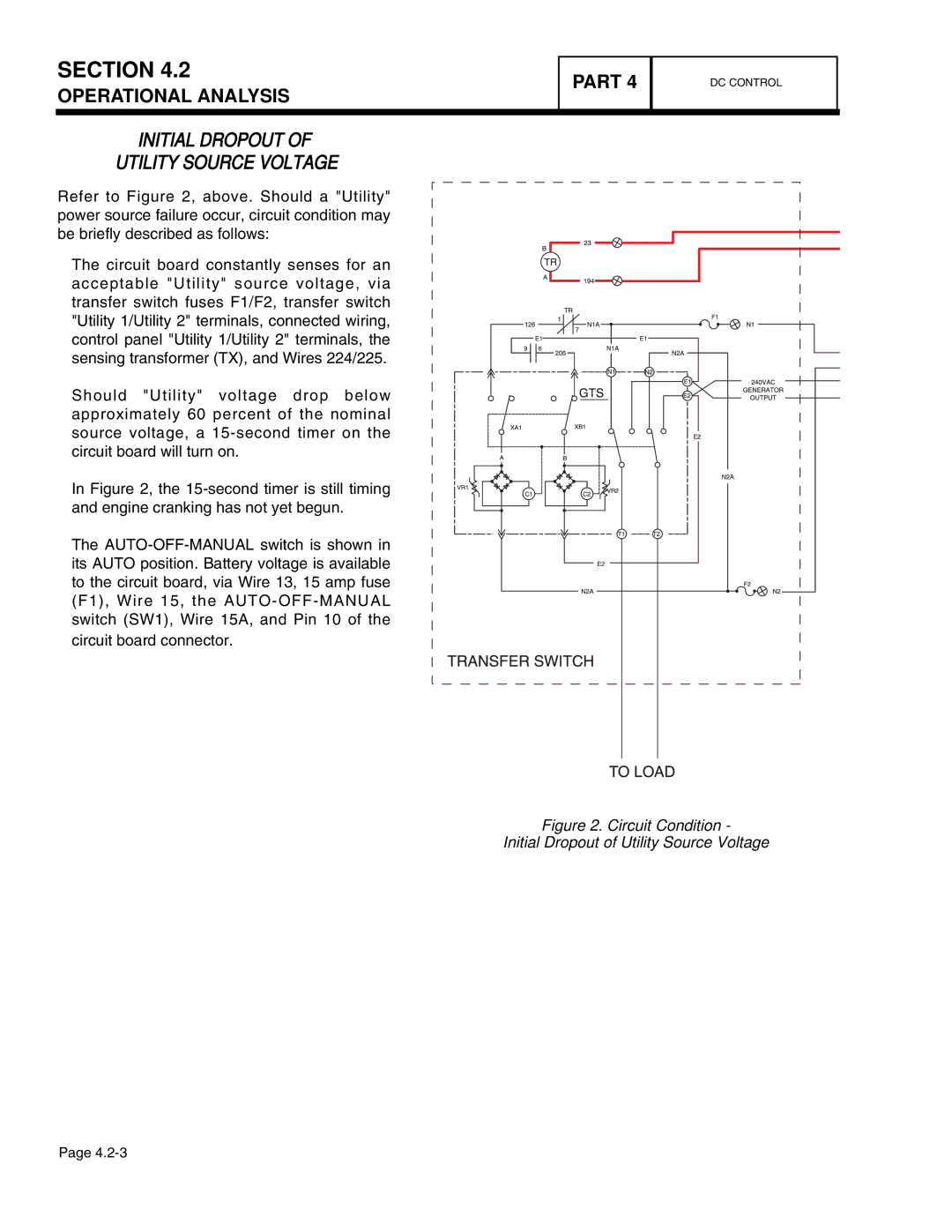
Circuit Condition Initial Dropout of Utility Source Voltage
Initial Dropout Utility Source Voltage
Section
Utility Voltage Dropout Engine Cranking
Section
Circuit Condition Engine Startup and Running
Engine Startup and Running
Section
Initial Transfer to Standby Source
Section
Circuit Condition Utility Voltage Restored
Utility Voltage Restored / RE Transfer to Utility
Section
Circuit Condition Retransfer to Utility and Engine Shutdown
Engine Shutdown
Operational Analysis
Troubleshooting Flow Charts Part
Troubleshooting Flow Charts
Section
Section
Section
Section
Section
Test 43- Test AUTO-OFF-MANUAL Switch
Test 41 Check Position of AUTO-OFF Manual Switch
Test 42 TRY a Manual Start
Set a VOM to measure DC voltage
Replace AUTO-OFF-MANUAL switch, if defective
Test 45- Check 15 AMP Fuse
Test 46- Check Battery
Inspect Battery Cables
Test Battery State of Charge
Test 48- Test Starter Contactor Relay V-TWIN only
Test 47 Check Wire 56 Voltage
Test Battery Condition
If battery voltage is not indicated in , go to Test
Starter Contactor Relay
Test 49- Test Starter Contactor
Checking the Pinion
Test 50- Test Starter Motor
Shorted, open or grounded armature
Conditions Affecting Starter Motor Performance
Test Bracket
Tachometer
Tools for Starter Performance Test
Measuring Current
Remove Starter Motor
Testing Starter Motor
Test 51 Check Fuel Supply Pressure
Testing Starter Motor Performance
Test 52 Test Fuel Solenoid
Test 53 Check Circuit Board Wire Output
Disconnect Wire 14 at the Fuel Solenoid FS
Set the AUTO-OFF-MANUAL switch to OFF
Test 55 Check for Ignition Spark
Test 54 Check Fuel Solenoid
Test 57- Check Engine Compression
Test 56 Check Spark Plugs
If sparking occurs but engine still wont start, go to Test
Test 59 Check and Adjust Ignition Magnetos
Test 58 Check Shutdown Wire
If ignition spark still has not occurred, proceed to Test
Setting Ignition Magneto Armature Air Gap
Do the following
Test 60- Check OIL Pressure Switch Wire
Check engine crankcase oil level
With oil level correct, try starting the engine
Remove the High Oil Temperature Switch
Test 61- Check High OIL Temperature Switch
Switch terminals
Replace switch if it fails the test
Procedure Intake and Exhaust
Test 62 Check and Adjust Valves
Test 63 Check Fuel Regulator
Test 64 Check Battery Charge Output
If voltage was not measured in , go to Test
Test 66 Check AC Voltage AT Battery Charger
Test 65 Check Transformer TX Voltage Output
Set a VOM to measure AC voltage
BCR
Test 68 Check Battery Charge Winding Harness
Test 70 Check Engine RUN Winding
Test 69 Check Battery Charger Wiring
Set VOM to measure frequency 63 HZ should be measured
Test 71 Check N1 and N2 Voltage
Test 73 Test SET Exercise Switch
AT the Circuit Board
Test 75 Check Battery Voltage Circuit
Test 74 Check Remote Start Wiring If Equipped
Test 76 Check Cranking and Running Circuits
Continuity
Test 77 Test Exercise Function
Part Operational Tests
Type Transfer Switches
Manual Transfer Switch Operation
Electrical Checks
Generator Tests Under Load
Verify that the AUTO-OFF-MANUAL switch is set to Auto
Setting the Exercise Timer
Checking Automatic Operation
Part Disassembly
Remove door
Major Disassembly
STATOR/ROTOR/ENGINE Removal
Major Disassembly
Follow Stator/Rotor/Engine removal procedures, Steps
Front Engine Access
Reverse the previous steps to re-assemble
Part Electrical Data
Model
Part SCHEMATIC, 7 KW Home Standby
Model 4456-0
Part SCHEMATIC, 12 & 15 KW Home Standby
Drawing #0D9013-C 1
Part Wiring DIAGRAM, 7 KW Home Standby
Drawing #0D9014-B 1
Drawing #0D9014-B 2
Model 4456-1
Part Wiring DIAGRAM, 12 & 15 KW Home Standby
Drawing #0D8501-B 1
Drawing #0D8501-B 2
Part
Electrical Data
Part
Page
Page
Xxxxxxxxxxxxxxxxxxxxxxxxxxx
Xxxxxxxxxxxxxxxxxxxxxxxxxxx Part
Procedure
Section