
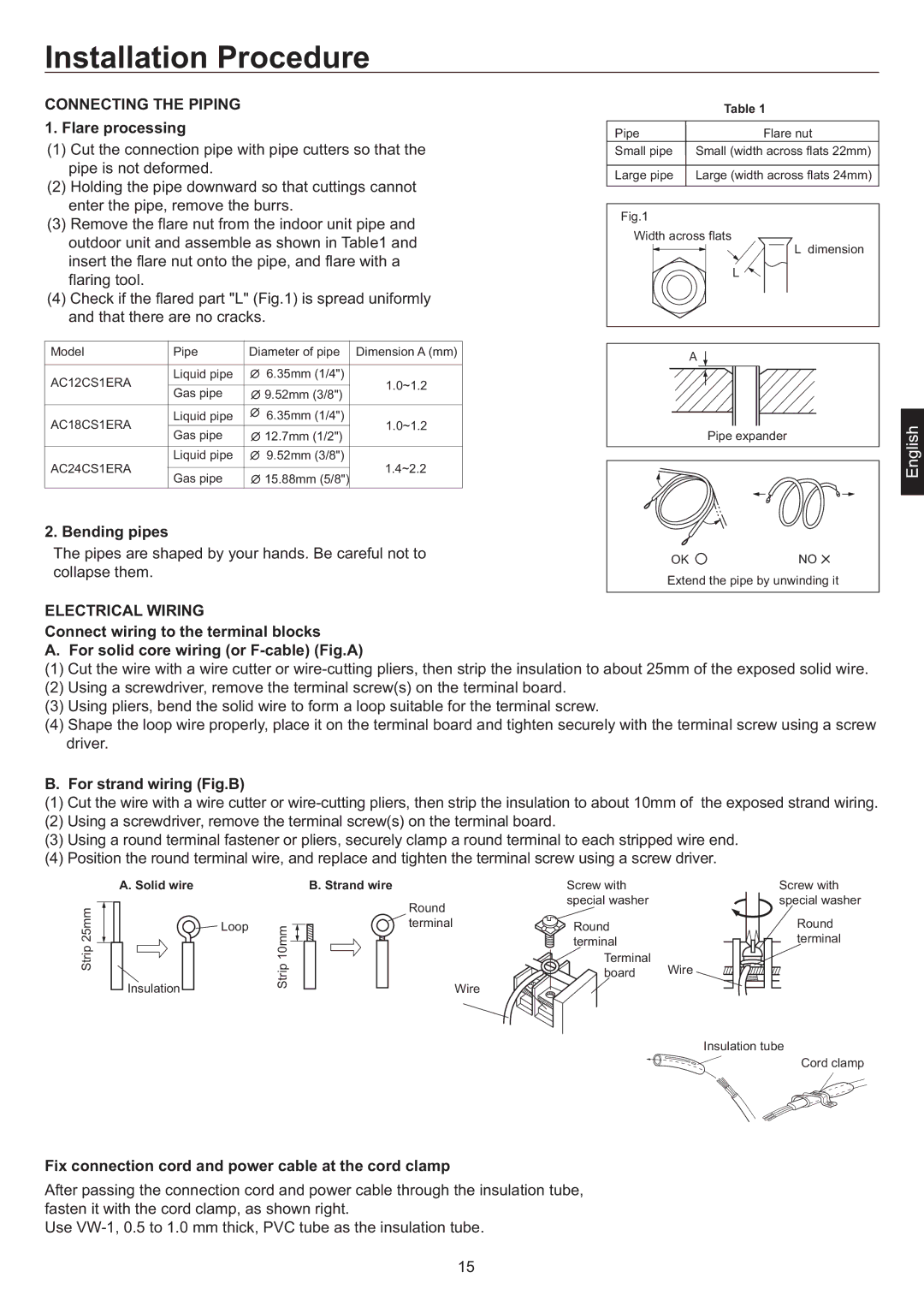
AC12CS1ERA, AC24CS1ERA, AC18CS1ERA specifications
The Haier AC series, which includes the AC24CS1ERA, AC18CS1ERA, and AC12CS1ERA, stands out in the realm of air conditioning units for their blend of advanced technology and user-friendly features. Each model is designed to cater to a variety of room sizes and cooling needs, ensuring a comfortable indoor environment regardless of outdoor conditions.The Haier AC24CS1ERA is a powerhouse, designed for larger spaces. With a cooling capacity of 2.0 tons, this model is equipped to efficiently cool sizable rooms while maintaining energy efficiency. The highlight of this model is its intelligent temperature control technology, which allows users to set their desired temperature quickly and accurately. The inverter technology enables smooth operation with minimal fluctuations in temperature. Additionally, it offers a quiet operation mode, perfect for bedrooms or study areas where noise can be a distraction.
The AC18CS1ERA is a mid-range option with a cooling capacity of 1.5 tons. It is ideal for medium-sized rooms, providing an optimal balance between performance and energy consumption. One of the standout features of this model is its multi-mode operation, which includes cooling, heating, dehumidifying, and fan modes. This versatility makes it suitable for year-round use, effectively coping with varying weather conditions. The inclusion of a user-friendly remote control enhances convenience, allowing adjustments from a distance.
For smaller spaces, the Haier AC12CS1ERA, with a cooling capacity of 1 ton, is an excellent choice. Its compact design makes it easy to install in rooms where space is limited. This model also incorporates eco-friendly refrigerants, aligning with growing environmental consciousness. The AC12CS1ERA features a sleek design that blends seamlessly with modern interiors while ensuring effective cooling performance. It also boasts easy maintenance features, such as a removable filter that can be easily cleaned to keep air quality high.
In terms of characteristics, all three models are equipped with high-efficiency compressors that optimize energy usage while delivering powerful cooling. Additionally, they come with advanced air filtration systems that help reduce dust and allergens, contributing to healthier indoor air quality. The sleek aesthetic of these units, combined with their robust functionality, illustrates Haier’s commitment to innovation and consumer satisfaction.
In summary, the Haier AC24CS1ERA, AC18CS1ERA, and AC12CS1ERA provide efficient cooling solutions tailored to different room sizes and needs. With intelligent features, energy-efficient technologies, and user-centric designs, these air conditioners are a top choice for consumers seeking reliable and stylish cooling options.