INSTALLATION
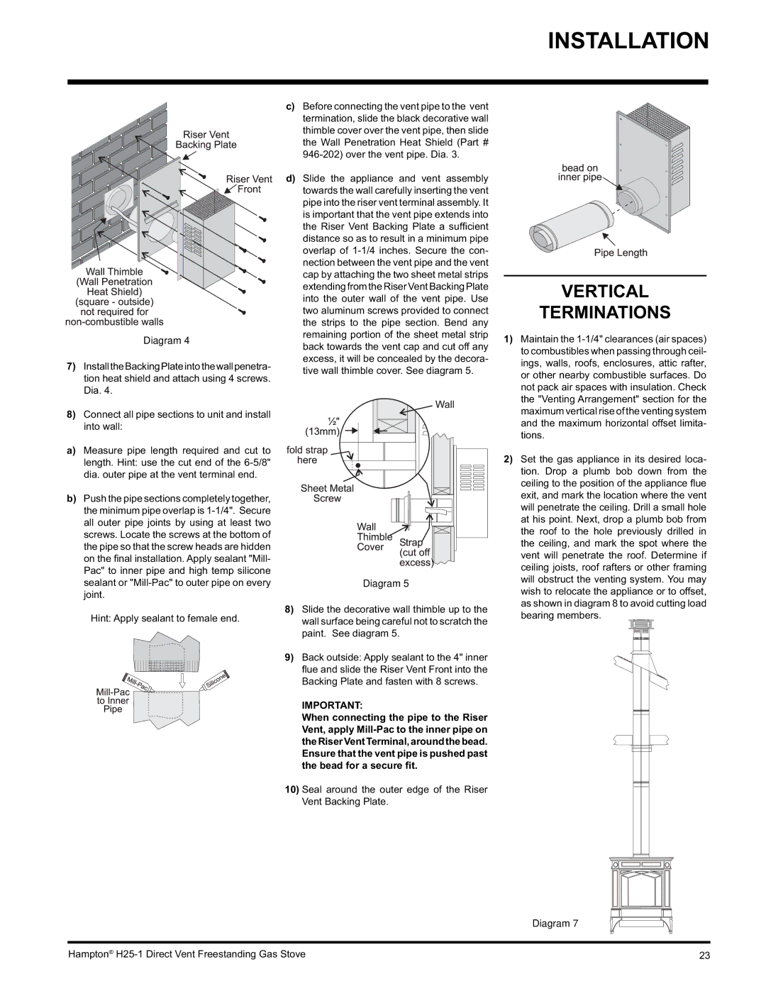
Diagram 4
7)InstalltheBackingPlateintothewallpenetra- tion heat shield and attach using 4 screws. Dia. 4.
8)Connect all pipe sections to unit and install into wall:
a)Measure pipe length required and cut to length. Hint: use the cut end of the
b)Push the pipe sections completely together, the minimum pipe overlap is
Hint: Apply sealant to female end.
c)Before connecting the vent pipe to the vent termination, slide the black decorative wall thimble cover over the vent pipe, then slide the Wall Penetration Heat Shield (Part #
d)Slide the appliance and vent assembly towards the wall carefully inserting the vent pipe into the riser vent terminal assembly. It is important that the vent pipe extends into the Riser Vent Backing Plate a suffi cient distance so as to result in a minimum pipe overlap of
Diagram 5
8)Slide the decorative wall thimble up to the wall surface being careful not to scratch the paint. See diagram 5.
9)Back outside: Apply sealant to the 4" inner fl ue and slide the Riser Vent Front into the Backing Plate and fasten with 8 screws.
IMPORTANT:
When connecting the pipe to the Riser Vent, apply
10)Seal around the outer edge of the Riser Vent Backing Plate.
VERTICAL
TERMINATIONS
1)Maintain the
2)Set the gas appliance in its desired loca- tion. Drop a plumb bob down from the ceiling to the position of the appliance fl ue exit, and mark the location where the vent will penetrate the ceiling. Drill a small hole at his point. Next, drop a plumb bob from the roof to the hole previously drilled in the ceiling, and mark the spot where the vent will penetrate the roof. Determine if ceiling joists, roof rafters or other framing will obstruct the venting system. You may wish to relocate the appliance or to offset, as shown in diagram 8 to avoid cutting load bearing members.
Diagram 7
Hampton® | 23 |