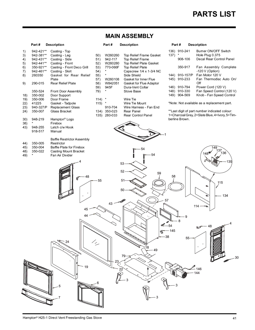
PARTS LIST
MAIN ASSEMBLY
Part # | Description | Part # | Description |
1)
3) | Casting - Leg | 50) | W260260 | Top Relief Frame Gasket | |
4) | Casting - Side | 51) | Top Relief Frame | ||
5) | Casting - Front | 52) | W260280 | Top Relief Plate Gasket | |
6) | Casting - Front Deco Grill | 53) | Top Relief Plate | ||
7) | Casting - Skirt | 54) | * | Capscrew 1/4 x | |
8) | 260350 | Gasket for Rear Relief | 55) | * | Side Shield |
|
| Plate | 57) | W260108 | Gasket for Inner Flue |
9) | Rear Relief Plate | 58) | W842051 | Gasket for Flue Adaptor | |
|
|
| 59) | 945F | |
| Front Door Assembly | 79) | * | Stove Base |
18)
19) | Door Frame | 114) | * | Wire Tie | |
22) | 41225 | Gasket - Tadpole | 115) | * | Wire Tie Mount |
23) | Replacement Glass |
| Wire Harness - Fan End | ||
24) | Glass Bracket | 134) | Rear Panel | ||
30) | Hampton® Logo | 135) | Rear Control Panel | ||
|
|
| |||
38) | * | Firebox |
|
|
|
43)
Baffl e Restrictor Assembly
44)
45)
48)
49) * | Fan Air Divider |
Part # Description
136)
137) * Hole Plug 0.375
144)
145)
146)
148)
149)
*Note: Not available as a replacement part.
**Last digit of part number indicated colour: 1=Charcoal Grey, 2=Slate Blue, 4=Ivory, 5=Tim- berline Brown.
Hampton® | 41 |
