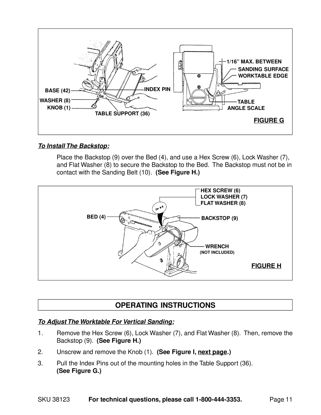
| 1/16” MAX. BETWEEN |
| SANDING SURFACE |
| WORKTABLE EDGE |
BASE (42) | INDEX PIN |
WASHER (8) | TABLE |
KNOB (1) | ANGLE SCALE |
| TABLE SUPPORT (36) |
| FIGURE G |
To Install The Backstop:
Place the Backstop (9) over the Bed (4), and use a Hex Screw (6), Lock Washer (7), and Flat Washer (8) to secure the Backstop to the Bed. The Backstop must not be in contact with the Sanding Belt (10). (See Figure H.)
HEX SCREW (6)
LOCK WASHER (7)
FLAT WASHER (8)
BED (4) |
| BACKSTOP (9) |
|
WRENCH
(NOT INCLUDED)
FIGURE H
OPERATING INSTRUCTIONS
To Adjust The Worktable For Vertical Sanding:
1.Remove the Hex Screw (6), Lock Washer (7), and Flat Washer (8). Then, remove the Backstop (9). (See Figure H.)
2.Unscrew and remove the Knob (1). (See Figure I, next page.)
3.Pull the Index Pins out of the mounting holes in the Table Support (36).
(See Figure G.)
SKU 38123 | For technical questions, please call | Page 11 |