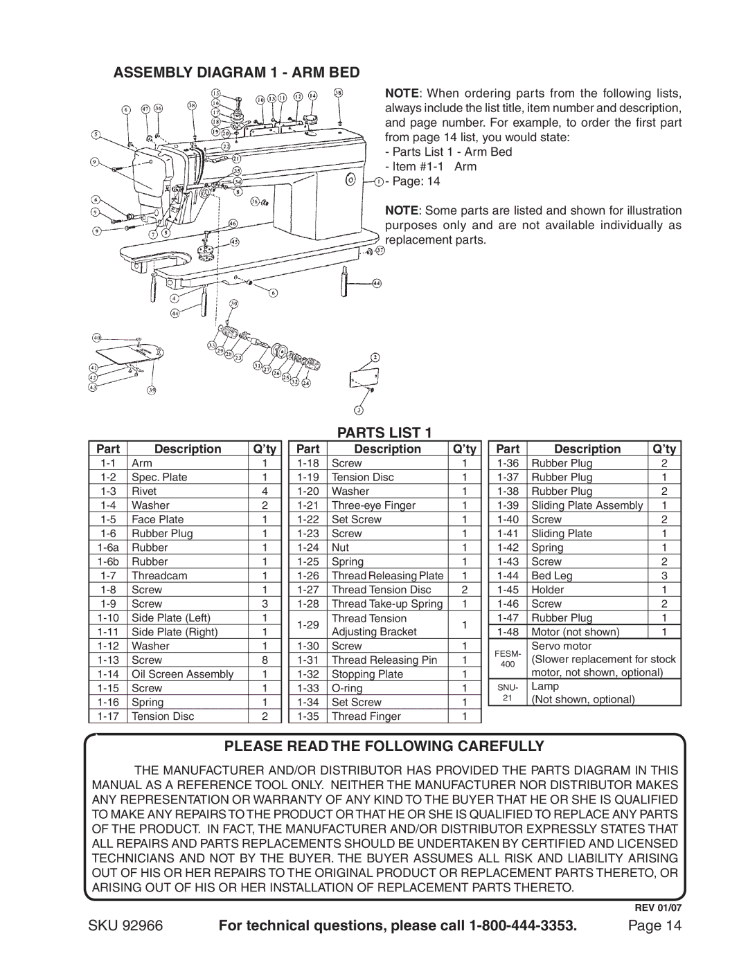
ASSEMBLY Diagram 1 - ARM BED
NOTE: When ordering parts from the following lists, always include the list title, item number and description, and page number. For example, to order the first part from page 14 list, you would state:
- Parts List 1 - Arm Bed - Item
- Page: 14
NOTE: Some parts are listed and shown for illustration purposes only and are not available individually as replacement parts.
PARTS LIST 1
Part | Description | Q’ty |
| Part | Description | Q’ty |
| Part | Description | Q’ty |
Arm | 1 |
| Screw | 1 |
| Rubber Plug | 2 | |||
Spec. Plate | 1 |
| Tension Disc | 1 |
| Rubber Plug | 1 | |||
Rivet | 4 |
| Washer | 1 |
| Rubber Plug | 2 | |||
Washer | 2 |
| 1 |
| Sliding Plate Assembly | 1 | ||||
Face Plate | 1 |
| Set Screw | 1 |
| Screw | 2 | |||
Rubber Plug | 1 |
| Screw | 1 |
| Sliding Plate | 1 | |||
Rubber | 1 |
| Nut | 1 |
| Spring | 1 | |||
Rubber | 1 |
| Spring | 1 |
| Screw | 2 | |||
Threadcam | 1 |
| Thread Releasing Plate | 1 |
| Bed Leg | 3 | |||
Screw | 1 |
| Thread Tension Disc | 2 |
| Holder | 1 | |||
Screw | 3 |
| Thread | 1 |
| Screw | 2 | |||
Side Plate (Left) | 1 |
| Thread Tension | 1 |
| Rubber Plug | 1 | |||
Side Plate (Right) | 1 |
| Adjusting Bracket |
| Motor (not shown) | 1 | ||||
|
|
|
| |||||||
Washer | 1 |
| Screw | 1 |
| FESM- | Servo motor |
| ||
Screw | 8 |
| Thread Releasing Pin | 1 |
| (Slower replacement for stock | ||||
|
|
|
|
|
|
|
| 400 | motor, not shown, optional) | |
Oil Screen Assembly | 1 |
| Stopping Plate | 1 | ||||||
|
|
| ||||||||
|
|
|
|
|
|
|
|
| Lamp |
|
Screw | 1 |
| 1 |
| SNU- |
| ||||
Spring | 1 |
| Set Screw | 1 |
| 21 | (Not shown, optional) |
| ||
|
|
|
| |||||||
|
|
|
|
|
|
|
|
|
|
|
Tension Disc | 2 |
| Thread Finger | 1 |
|
|
|
| ||
PLEASE READ THE FOLLOWING CAREFULLY
THE MANUFACTURER AND/OR DISTRIBUTOR HAS PROVIDED THE PARTS DIAGRAM IN THIS MANUAL AS A REFERENCE TOOL ONLY. NEITHER THE MANUFACTURER NOR DISTRIBUTOR MAKES ANY REPRESENTATION OR WARRANTY OF ANY KIND TO THE BUYER THAT HE OR SHE IS QUALIFIED TO MAKE ANY REPAIRS TO THE PRODUCT OR THAT HE OR SHE IS QUALIFIED TO REPLACE ANY PARTS OF THE PRODUCT. IN FACT, THE MANUFACTURER AND/OR DISTRIBUTOR EXPRESSLY STATES THAT ALL REPAIRS AND PARTS REPLACEMENTS SHOULD BE UNDERTAKEN BY CERTIFIED AND LICENSED TECHNICIANS AND NOT BY THE BUYER. THE BUYER ASSUMES ALL RISK AND LIABILITY ARISING OUT OF HIS OR HER REPAIRS TO THE ORIGINAL PRODUCT OR REPLACEMENT PARTS THERETO, OR ARISING OUT OF HIS OR HER INSTALLATION OF REPLACEMENT PARTS THERETO.
REV 01/07
SKU 92966 | For technical questions, please call | Page 14 |