System Configuration
Input Setup
The first step in configuring the AVR5000 is to select an input. This may be done by pressing the front panel Input Source Selector ! until the desired input’s name appears momen- tarily in the Main Information Display Y, and the green LED lights next to the input’s name in the front panel Input Indicators . The input may also be selected by pressing the appropriate Input Selector on the remote control 46.
When using the
Euntil the desired input name appears in the highlighted video, as well as being indicated in the front panel Input Indicators by the green LED next to the desired input name. If the input will use the standard left/right analog inputs, no further adjustment is needed.
* I N / O U T S E T U P *
I N P U T |
| : | V I D E O 1 | ||
|
|
| |||
D I G I T A L | I N : | A N A L O G |
| ||
|
|
| |||
C O A X I A L | 3 | : | I N | O U T | |
|
|
|
|
|
|
V I D E O 4 |
| : | I N | O U T | |
R E T U R N T O | M E N U | ||||
Figure 2
If you wish to associate one of the digital inputs with the selected input source, press the ¤ but- ton Don the remote while the IN/OUT SETUP menu (Figure 2) is on the screen, and note that the
To change the digital input associated with the input selected at any time using the discrete function buttons and the
An exclusive Harman Kardon feature is the abili- ty to switch front panel jacks from their normal use as inputs to output connections so that portable recording devices may easily be con- nected. The front panel analog Video 4 Jacks
^are normally set as an input for use with camcorders, video games and other portable audio/video products, but they may be switched to an output for connection to portable audio/video recorders. To temporarily switch them to outputs, select the IN/OUT SETUP menu. Press the ¤ button Duntil the
VIDEO 4 line. Press the › button so that the word OUT is highlighted. Note that the Input/Output Status Indicator $ between the S and Composite video jacks will turn red, indicating that the analog Video 4 jacks ^are now record outputs.
On the AVR5000, the Coaxial 3 Digital Jack
%is normally an input, but it may also be switched to a digital output for use with CD- R/RW decks, MD recorders or other digital audio recorders. To change the jack to an output, press the ⁄/¤ buttons Dwhile the IN/OUT SETUP menu is on the screen so that the › cursor is next to COAXIAL 3. Then press
the ‹/› buttons E/ so that the word OUT is highlighted. Note that the Digital Coax 3 Status Indicator $will turn red, indicating that the jack is now a record output.
Note: A signal will be sent to this jack only when the input selected for use by the AVR5000 is digital. Digital signals will be passed through regardless of their format, and which digital input (optical or coax) they are fed from. However, analog signals are not converted to digital, and the format of the signal (e.g., PCM, Dolby Digital or DTS) may not be changed.
Selection of the Digital Coax 3 jack as an output will remain effective as long as the AVR 5000 is on. However, once the unit is turned off, the jack will revert to its normal use as an input when the unit is turned on again.
Surround Setup
Once the input setup has been completed, the next step for that input is to set the surround mode you wish to use with that input. Since sur- round modes are a matter of personal taste, feel free to select any mode you wish – you may change it later. The Surround Mode chart on page 28 may help you select the mode best suit- ed to the input source selected. However, to make it easier to establish the initial parameters for the AVR5000, it is best to select Dolby Pro Logic for most analog inputs and Dolby Digital for inputs connected to digital sources. In the case of inputs such as a CD Player, Tape Deck or Tuner, you may wish to set the mode to Stereo, if that is your preferred listening mode for stan- dard stereo sources, where it is unlikely that sur-
round encoded material will be used. Alternatively, the 5 Channel Stereo or Logic 7 Music mode may also be a good choice for
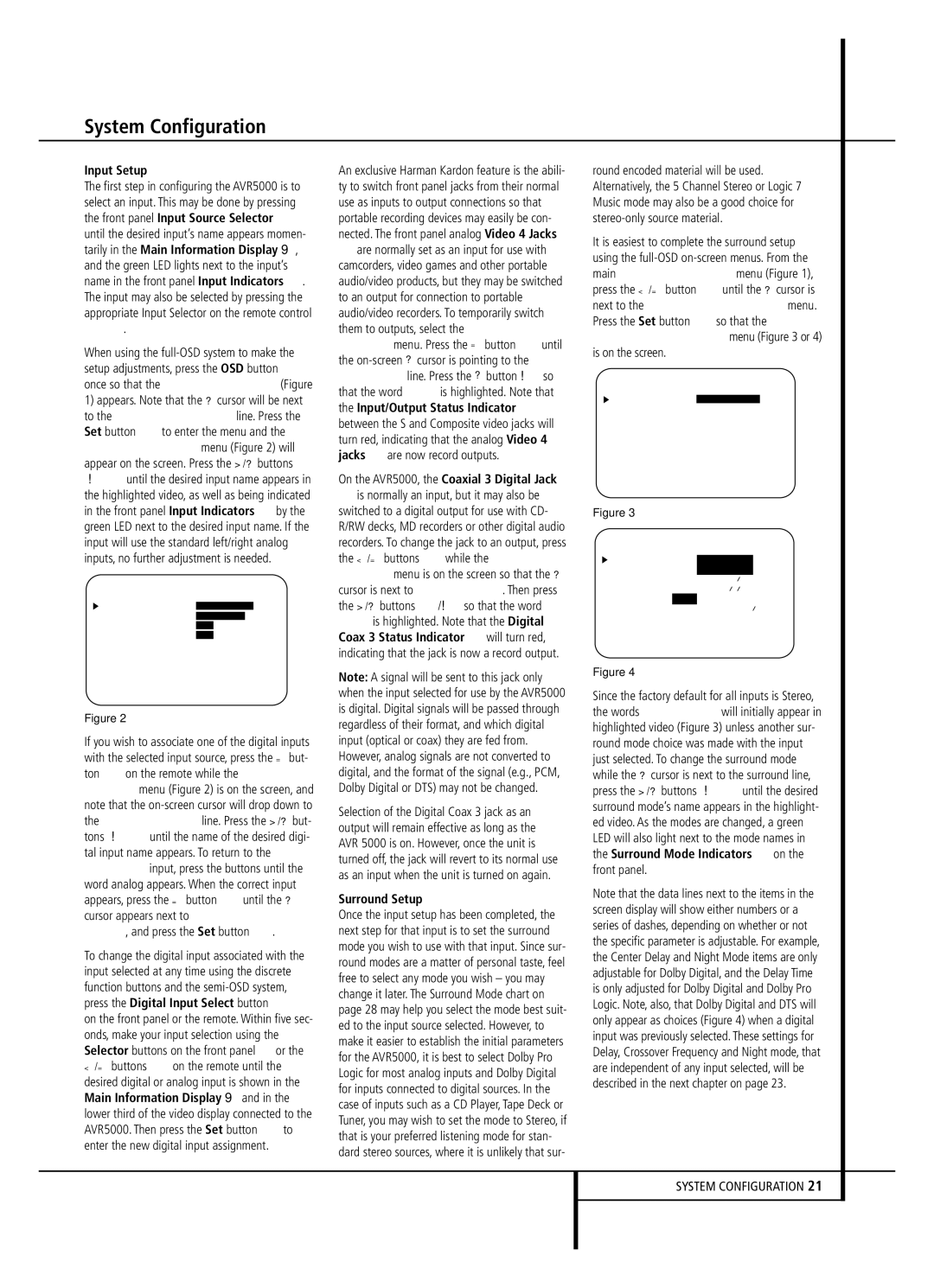
It is easiest to complete the surround setup using the
* S U R R O U N D S E T U P *
S U R R O U N D : S U R R O F F
C E N T E R D E L A Y :
S U R R D E L A Y :
N I G H T :
R E T U R N T O M E N U
Figure 3
* S U R R O U N D | S E T U P * | |||
|
|
|
| |
S U R R O U N D : | D O L B Y |
|
| |
|
| D I G I T A L |
| |
C E N T E R D E L A Y : | 0 M S | |||
S U R R | D E L A Y : 0 0 M S | |||
N I G H T : | O F F | M I D M A X | ||
R E T U R N T O | M E N U |
|
| |
|
|
|
|
|
Figure 4
Since the factory default for all inputs is Stereo, the words SURR OFF will initially appear in highlighted video (Figure 3) unless another sur- round mode choice was made with the input just selected. To change the surround mode while the › cursor is next to the surround line, press the ‹/› buttons E until the desired surround mode’s name appears in the highlight- ed video. As the modes are changed, a green LED will also light next to the mode names in the Surround Mode Indicators ˜on the front panel.
Note that the data lines next to the items in the screen display will show either numbers or a series of dashes, depending on whether or not the specific parameter is adjustable. For example, the Center Delay and Night Mode items are only adjustable for Dolby Digital, and the Delay Time is only adjusted for Dolby Digital and Dolby Pro Logic. Note, also, that Dolby Digital and DTS will only appear as choices (Figure 4) when a digital input was previously selected. These settings for Delay, Crossover Frequency and Night mode, that are independent of any input selected, will be described in the next chapter on page 23.