ASSEMBLY
Assembly requires two people.Place the treadmill in a cleared area and remove all packing materials. Do not dispose of the packing materials until the treadmill is assembled.
Note: The underside of the treadmill walking belt is coated with
Assembly requires your own phillips screwdriver | , rubber mallet | and wire | |
cutters | . |
|
|
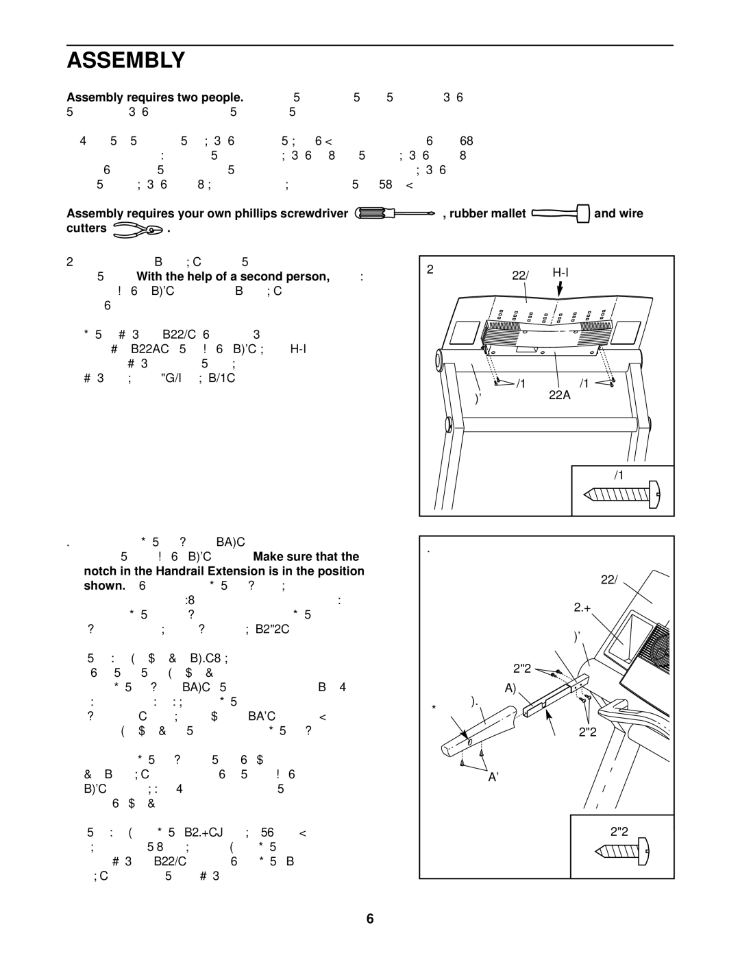
1. Cut the plastic ties (not shown) from the sides of the
treadmill. With the help of a second person, | carefully |
raise the Uprights (65) until the Wheels (not shown) are | |
resting on the floor. |
|
Hold the Book Plate (114) against the back of the | |
Console Base (117) and the Upright (65) | with the “V” |
shape of the Book Plate positioned as shown. Attach the Book Plate with four 3/4” Screws (40).
2. Insert one of the Handrail Extensions (76) into the post on
the left side of the Upright (65). | Make sure that the | ||
notch in the Handrail Extension is in the position | |||
shown. | Align the holes in the Handrail Extension with the | ||
holes in the post. If necessary, | use a rubber mallet to fully | ||
insert | the Handrail | Extension. Attach | the Handrail |
Extension to the post with four Extension Screws (131).
Identify the Left Foam Grip (62), which has a hole in the right side. Slide the Left Foam Grip as far as possible
onto the Handrail Extension (76) and the | post. (Note: It | |
may be helpful to apply soapy water to the Handrail |
| |
Extension | .) Press two Plastic Fasteners (75) into the bot- | |
tom of the Left Foam Grip and the | Handrail Extension. | |
Attach the other Handrail Extension and the Right Foam
Grip (not shown) to the post on the right side of the Upright
(65)in the same way. Note: There is not a hole in the side of the Right Foam Grip.
Identify the Left Cup Holder (128); the lower edge is nar- rower on the left side, as shown. Press the Left Cup Holder
into the Book Plate (114). Press the Right Cup Holder (not shown) into the other side of the Book Plate.
1 | 114 | “V” |
|
| 40 | 117 | 40 |
| 65 |
| |
|
|
| 40 |
2 |
|
|
|
|
|
| 114 |
|
|
| 128 |
|
| Post | 65 |
|
|
| |
| 131 |
|
|
| 76 |
|
|
Hole | 62 |
|
|
|
|
| |
|
| Notch | 131 |
|
|
| |
| 75 |
|
|
|
|
| 131 |
6