G. Vertical Termination
1. Direct Vent Pipe
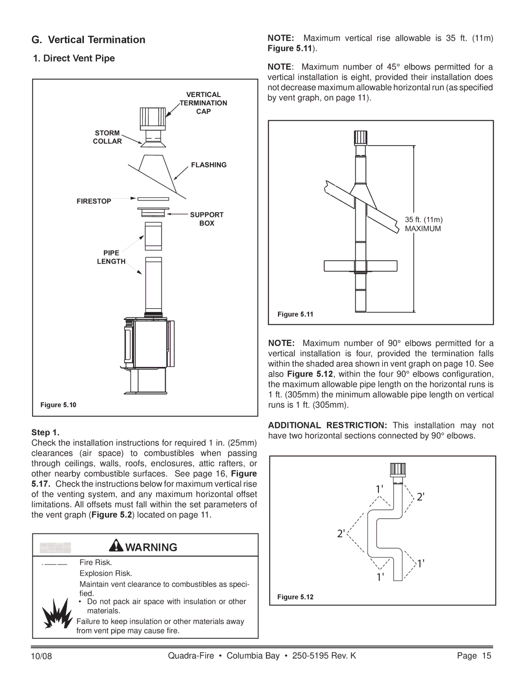
VERTICAL
TERMINATION
CAP
STORM
COLLAR![]()
FLASHING
FIRESTOP
![]() SUPPORT
SUPPORT
BOX
PIPE
LENGTH
Figure 5.10
Step 1.
Check the installation instructions for required 1 in. (25mm) clearances (air space) to combustibles when passing through ceilings, walls, roofs, enclosures, attic rafters, or other nearby combustible surfaces. See page 16, Figure
NOTE: Maximum vertical rise allowable is 35 ft. (11m) Figure 5.11).
NOTE: Maximum number of 45° elbows permitted for a vertical installation is eight, provided their installation does not decrease maximum allowable horizontal run (as specified by vent graph, on page 11).
35 ft. (11m)
MAXIMUM
Figure 5.11
NOTE: Maximum number of 90° elbows permitted for a vertical installation is four, provided the termination falls within the shaded area shown in vent graph on page 10. See also Figure 5.12, within the four 90° elbows configuration, the maximum allowable pipe length on the horizontal runs is 1 ft. (305mm) the minimum allowable pipe length on vertical runs is 1 ft. (305mm).
ADDITIONAL RESTRICTION: This installation may not have two horizontal sections connected by 90° elbows.
5.17.Check the instructions below for maximum vertical rise of the venting system, and any maximum horizontal offset limitations. All offsets must fall within the set parameters of the vent graph (Figure 5.2) located on page 11.
WARNING
Fire Risk.
1'
2'
2'
1'
Explosion Risk.
Maintain vent clearance to combustibles as speci- fied.
•Do not pack air space with insulation or other materials.
Failure to keep insulation or other materials away from vent pipe may cause fire.
1'
Figure 5.12
10/08 | Page 15 |