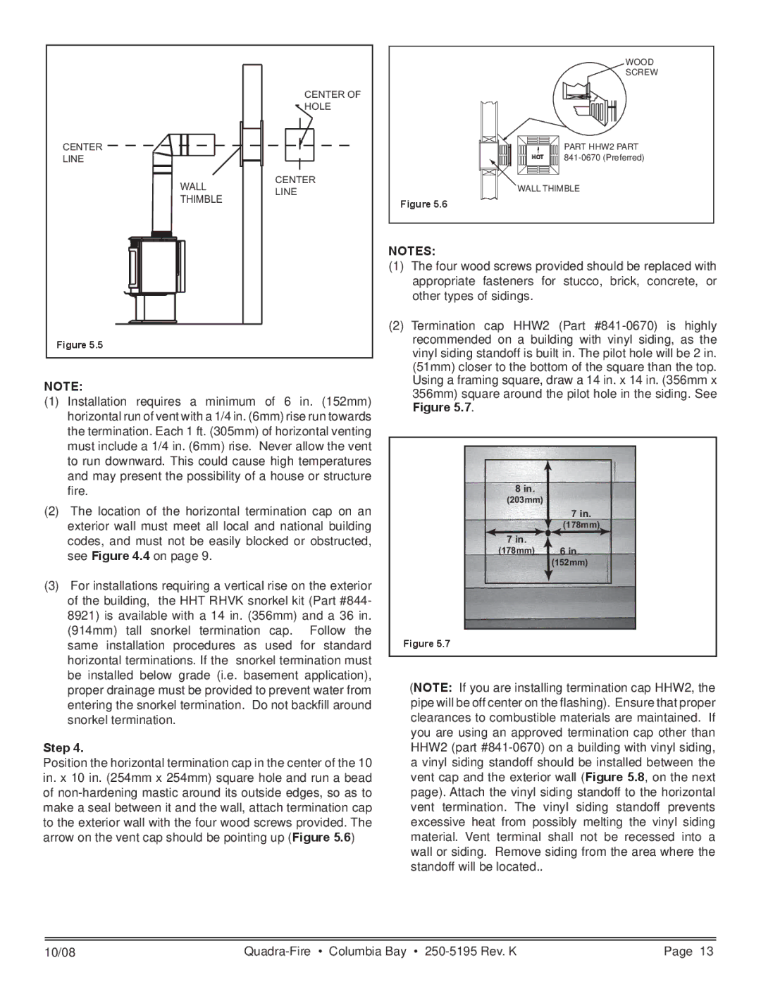
CENTER OF
HOLE
CENTER
LINE
CENTER
WALLLINE
THIMBLE
Figure 5.5
NOTE:
(1)Installation requires a minimum of 6 in. (152mm) horizontal run of vent with a 1/4 in. (6mm) rise run towards the termination. Each 1 ft. (305mm) of horizontal venting must include a 1/4 in. (6mm) rise. Never allow the vent to run downward. This could cause high temperatures and may present the possibility of a house or structure fire.
(2)The location of the horizontal termination cap on an exterior wall must meet all local and national building codes, and must not be easily blocked or obstructed, see Figure 4.4 on page 9.
(3)For installations requiring a vertical rise on the exterior of the building, the HHT RHVK snorkel kit (Part #844- 8921) is available with a 14 in. (356mm) and a 36 in. (914mm) tall snorkel termination cap. Follow the same installation procedures as used for standard horizontal terminations. If the snorkel termination must be installed below grade (i.e. basement application), proper drainage must be provided to prevent water from entering the snorkel termination. Do not backfill around snorkel termination.
Step 4.
Position the horizontal termination cap in the center of the 10 in. x 10 in. (254mm x 254mm) square hole and run a bead of
WOOD
SCREW
PART HHW2 PART
HOT
WALL THIMBLE
Figure 5.6
NOTES:
(1)The four wood screws provided should be replaced with appropriate fasteners for stucco, brick, concrete, or other types of sidings.
(2)Termination cap HHW2 (Part
8 in. |
|
(203mm) |
|
| 7 in. |
| (178mm) |
7 in. | 6 in. |
(178mm) | |
| (152mm) |
Figure 5.7
(NOTE: If you are installing termination cap HHW2, the pipe will be off center on the flashing). Ensure that proper clearances to combustible materials are maintained. If you are using an approved termination cap other than HHW2 (part
10/08 | Page 13 |