Step 2.
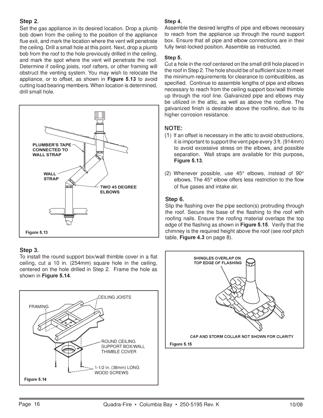
Set the gas appliance in its desired location. Drop a plumb bob down from the ceiling to the position of the appliance flue exit, and mark the location where the vent will penetrate the ceiling. Drill a small hole at this point. Next, drop a plumb bob from the roof to the hole previously drilled in the ceiling, and mark the spot where the vent will penetrate the roof. Determine if ceiling joists, roof rafters, or other framing will obstruct the venting system. You may wish to relocate the appliance, or to offset, as shown in Figure 5.13 to avoid cutting load bearing members. When location is determined, drill small hole.
PLUMBER'S TAPE
CONNECTED TO
WALL STRAP
WALL ![]()
STRAP
TWO 45 DEGREE
ELBOWS
Figure 5.13
Step 4.
Assemble the desired lengths of pipe and elbows necessary to reach from the appliance up through the round support box. Ensure that all pipe and elbow connections are in their fully
Step 5.
Cut a hole in the roof centered on the small drill hole placed in the roof in Step 2. The hole should be of sufficient size to meet the minimum requirements for clearance to combustibles, as specified. Continue to assemble lengths of pipe and elbows necessary to reach from the ceiling support box/wall thimble up through the roof line. Galvanized pipe and elbows may be utilized in the attic, as well as above the roofline. The galvanized finish is desirable above the roofline, due to its higher corrosion resistance.
NOTE:
(1) If an offset is necessary in the attic to avoid obstructions, it is important to support the vent pipe every 3 ft. (914mm) to avoid excessive stress on the elbows, and possible separation. Wall straps are available for this purpose,
Figure 5.13.
(2)Whenever possible, use 45° elbows, instead of 90° elbows. The 45° elbow offers less restriction to the flow of flue gases and intake air.
Step 6.
Slip the flashing over the pipe section(s) protruding through the roof. Secure the base of the flashing to the roof with roofing nails. Ensure the roofing material overlaps the top edge of the flashing as shown in Figure 5.15. Verify that the chimney is the required height above the roof (see roof pitch table, Figure 4.3 on page 8).
Step 3.
To install the round support box/wall thimble cover in a flat ceiling, cut a 10 in. (254mm) square hole in the ceiling, centered on the hole drilled in Step 2. Frame the hole as shown in Figure 5.14.
CEILING JOISTS
FRAMING
ROUND CEILING
SUPPORT BOX/WALL
THIMBLE COVER
![]()
WOOD SCREWS
Figure 5.14
SHINGLES OVERLAP ON
TOP EDGE OF FLASHING
CAP AND STORM COLLAR NOT SHOWN FOR CLARITY
Figure 5.15
Page 16 | 10/08 |