F. Horizontal Termination
HHW2 - Recommended for optimum performance.
90DEGREE ELBOW
PIPE LENGTH | WALL WALL THIMBLE |
| |
PIPE | THIMBLE |
COVER | |
LENGTH |
|
Figure 5.3
Step 1.
Determine the desired location of the appliance. Check to ensure that wall studs or roof rafters are not in the way when the venting system is attached. If this is the case, you may want to adjust the location of the appliance.
![]() WARNING
WARNING
Fire Hazard.
Exhaust Fume Risk.
Impaired Performance of Appliance.
•Ensure vent components are locked together correctly.
•Pipe may separate if not properly joined.
Step 2.
Direct vent pipe is designed with a locking connection. To connect the venting system to the appliance flue outlet, a
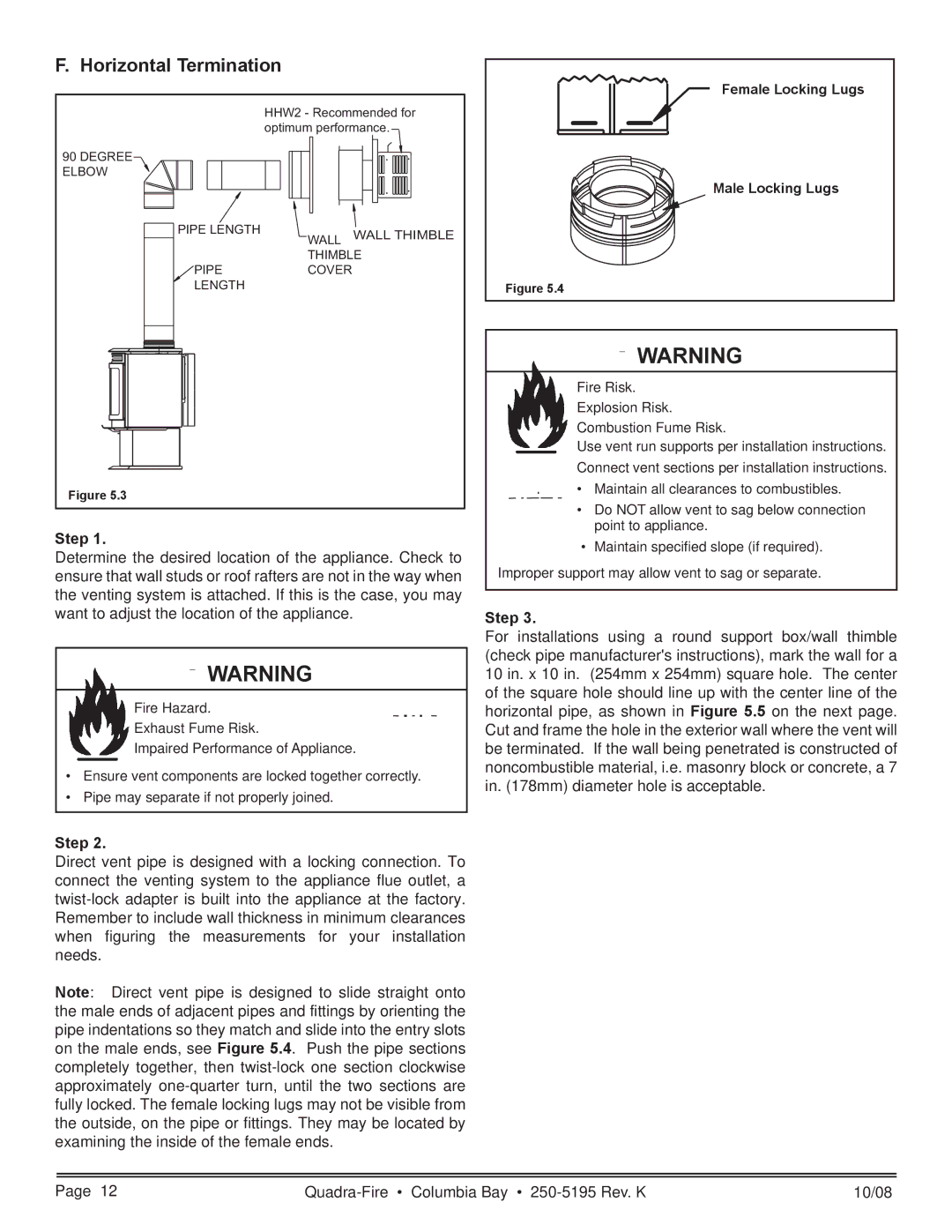
Note: Direct vent pipe is designed to slide straight onto the male ends of adjacent pipes and fittings by orienting the pipe indentations so they match and slide into the entry slots on the male ends, see Figure 5.4. Push the pipe sections completely together, then
Female Locking Lugs
Male Locking Lugs
Figure 5.4
![]() WARNING
WARNING
Fire Risk. Explosion Risk. Combustion Fume Risk.
Use vent run supports per installation instructions. Connect vent sections per installation instructions.
•Maintain all clearances to combustibles.
•Do NOT allow vent to sag below connection point to appliance.
•Maintain specified slope (if required).
Improper support may allow vent to sag or separate.
Step 3.
For installations using a round support box/wall thimble (check pipe manufacturer's instructions), mark the wall for a 10 in. x 10 in. (254mm x 254mm) square hole. The center of the square hole should line up with the center line of the horizontal pipe, as shown in Figure 5.5 on the next page. Cut and frame the hole in the exterior wall where the vent will be terminated. If the wall being penetrated is constructed of noncombustible material, i.e. masonry block or concrete, a 7 in. (178mm) diameter hole is acceptable.
Page 12 | 10/08 |