D. How to Use the Vent Graph
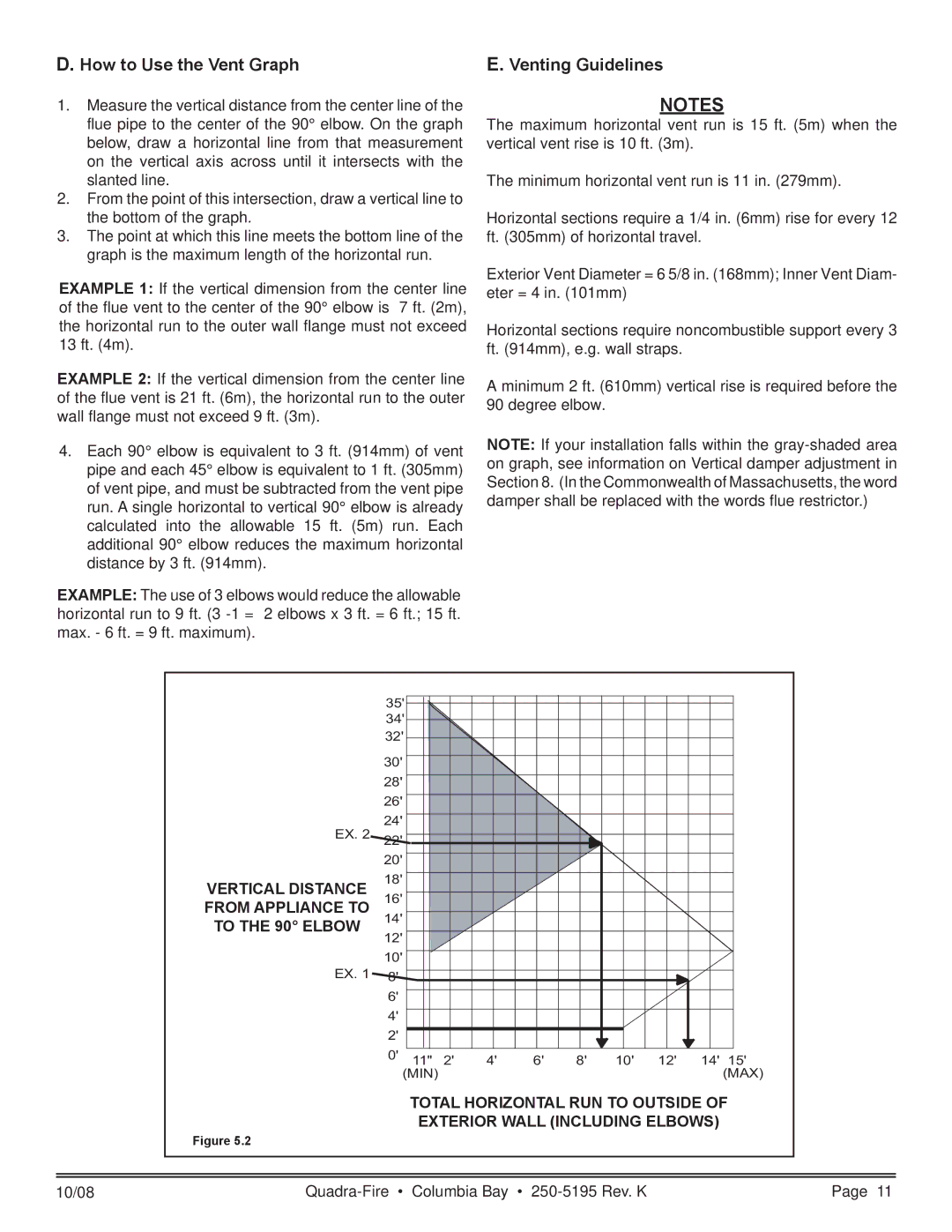
1.Measure the vertical distance from the center line of the flue pipe to the center of the 90° elbow. On the graph below, draw a horizontal line from that measurement on the vertical axis across until it intersects with the slanted line.
2.From the point of this intersection, draw a vertical line to the bottom of the graph.
3.The point at which this line meets the bottom line of the graph is the maximum length of the horizontal run.
EXAMPLE 1: If the vertical dimension from the center line of the flue vent to the center of the 90° elbow is 7 ft. (2m), the horizontal run to the outer wall flange must not exceed 13 ft. (4m).
EXAMPLE 2: If the vertical dimension from the center line of the flue vent is 21 ft. (6m), the horizontal run to the outer wall flange must not exceed 9 ft. (3m).
4.Each 90° elbow is equivalent to 3 ft. (914mm) of vent pipe and each 45° elbow is equivalent to 1 ft. (305mm) of vent pipe, and must be subtracted from the vent pipe run. A single horizontal to vertical 90° elbow is already calculated into the allowable 15 ft. (5m) run. Each additional 90° elbow reduces the maximum horizontal distance by 3 ft. (914mm).
EXAMPLE: The use of 3 elbows would reduce the allowable horizontal run to 9 ft. (3
E. Venting Guidelines
NOTES
The maximum horizontal vent run is 15 ft. (5m) when the vertical vent rise is 10 ft. (3m).
The minimum horizontal vent run is 11 in. (279mm).
Horizontal sections require a 1/4 in. (6mm) rise for every 12 ft. (305mm) of horizontal travel.
Exterior Vent Diameter = 6 5/8 in. (168mm); Inner Vent Diam- eter = 4 in. (101mm)
Horizontal sections require noncombustible support every 3 ft. (914mm), e.g. wall straps.
A minimum 2 ft. (610mm) vertical rise is required before the 90 degree elbow.
NOTE: If your installation falls within the
| 35' |
|
|
|
|
|
|
|
|
|
| 34' |
|
|
|
|
|
|
|
|
|
| 32' |
|
|
|
|
|
|
|
|
|
| 30' |
|
|
|
|
|
|
|
|
|
| 28' |
|
|
|
|
|
|
|
|
|
| 26' |
|
|
|
|
|
|
|
|
|
EX. 2 | 24' |
|
|
|
|
|
|
|
|
|
22' |
|
|
|
|
|
|
|
|
| |
| 20' |
|
|
|
|
|
|
|
|
|
VERTICAL DISTANCE | 18' |
|
|
|
|
|
|
|
|
|
FROM APPLIANCE TO | 16' |
|
|
|
|
|
|
|
|
|
TO THE 90° ELBOW | 14' |
|
|
|
|
|
|
|
|
|
12' |
|
|
|
|
|
|
|
|
| |
|
|
|
|
|
|
|
|
|
| |
EX. 1 | 10' |
|
|
|
|
|
|
|
|
|
8' |
|
|
|
|
|
|
|
|
| |
| 6' |
|
|
|
|
|
|
|
|
|
| 4' |
|
|
|
|
|
|
|
|
|
| 2' |
|
|
|
|
|
|
|
|
|
| 0' | 11" | 2' | 4' | 6' | 8' | 10' | 12' | 14' | 15' |
| (MIN) |
|
|
|
|
|
|
| (MAX) | |
TOTAL HORIZONTAL RUN TO OUTSIDE OF
EXTERIOR WALL (INCLUDING ELBOWS)
Figure 5.2
10/08 | Page 11 |