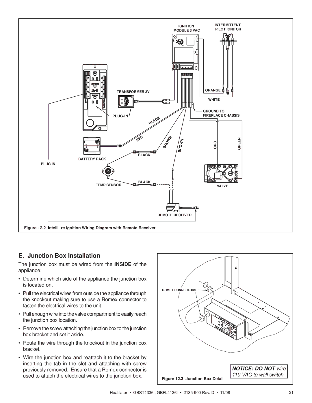
GBST4336I, GBFL4136I specifications
Hearth and Home Technologies has made significant strides in the realm of contemporary heating solutions with their innovative products, the GBST4336I and GBFL4136I fireplace inserts. These models exemplify a blend of cutting-edge technology, aesthetic design, and user-friendly features aimed at enhancing the home heating experience.The GBST4336I, known for its striking design and powerful performance, offers a modern solution to traditional heating methods. This model showcases a large viewing area, providing an expansive glimpse into the mesmerizing flames. Its efficient combustion system allows for exceptional heat output while minimizing emissions, making it an eco-friendly choice for homeowners. The insert is designed to fit seamlessly into most existing fireplace spaces, significantly enhancing the ambiance and warmth of any living area.
On the other hand, the GBFL4136I model is tailored for those seeking a more traditional wood-burning experience combined with modern efficiency. This insert features an impressive firebox capacity, allowing users to load more wood for longer burn times. The innovative air wash system keeps the glass clean, ensuring an unobstructed view of the fire. Additionally, the optional blower enhances heat circulation throughout the room, making it perfect for large spaces.
Both models are equipped with advanced technologies that contribute to their reliability and performance. The adjustable burn settings allow users to regulate heat output based on their specific needs, making these inserts versatile for different settings. Furthermore, they include the latest in safety features such as automatic shut-off capabilities, ensuring peace of mind while enjoying the warmth of the fire.
Aesthetically, both the GBST4336I and GBFL4136I come with customizable options, allowing homeowners to choose from various trim and finish choices to fit their home décor. The modern design elements, combined with classic fireplace features, ensure that these inserts not only heat the space but also serve as a stunning focal point in any room.
In summary, Hearth and Home Technologies' GBST4336I and GBFL4136I fireplace inserts stand out for their exceptional design, advanced technology, and practicality. They cater to the needs of modern homeowners by offering efficient heating solutions while maintaining an inviting and stylish atmosphere. With features that prioritize performance and safety, these inserts are an excellent choice for anyone looking to enhance their living space with the warmth and beauty of a fire.

