Step 9.
Twist-lock the flue cap and seal.
Note: For
NAILS
CEILING FIRESTOP
MIN. 25.4 cm
CLEARANCE
MIN. 25.4 cm
CLEARANCE
MIN. 25.4 cm
CLEARANCE
MIN. 25.4 cm
CLEARANCE
Figure 5.25
![]() WARNING
WARNING
Fire Risk.
Explosion Risk.
• Any occupied areas above the first floor, including closets and storage spaces, which the vertical flue passed through must be enclosed. The enclosure may be framed and sheetrocked with standard construction materials; however, refer to these installation instructions for the minimum allowable clearance between the outside of the flue pipe and the combustible surfaces of the enclosure. Do not fill any of the required air space with insulation.
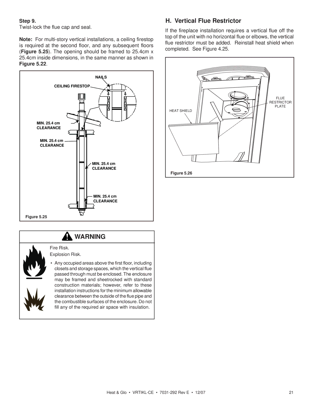
H. Vertical Flue Restrictor
If the fireplace installation requires a vertical flue off the top of the unit with no horizontal flue or elbows, the vertical flue restrictor must be added. Reinstall heat shield when completed. See Figure 4.25.
FLUE |
RESTRICTOR |
PLATE |
HEAT SHIELD |
Figure 5.26 |
Heat & Glo • | 21 |