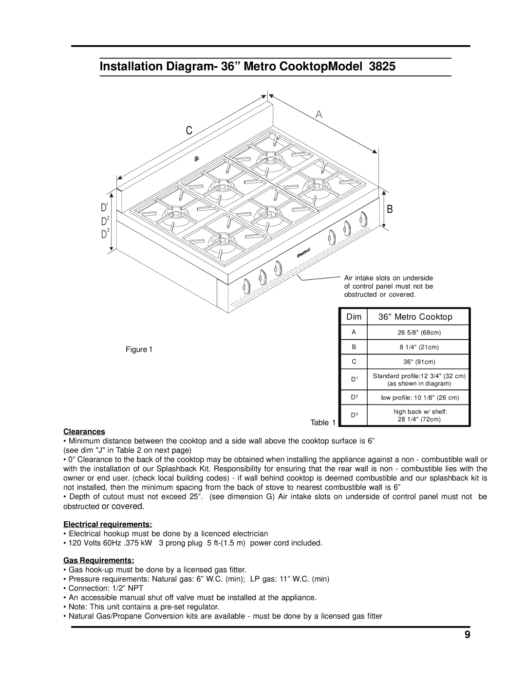
3800-3820, 3805-3825 specifications
Heartland Bakeware has emerged as a frontrunner in the culinary world, known for its exceptional products designed for both amateur and professional bakers. The Heartland Bakeware series, including models 3805, 3825, 3800, and 3820, showcases impressive innovation and functionality that cater to a wide range of baking needs.One of the standout features of Heartland Bakeware is its high-quality materials. Constructed from heavy-duty, non-stick coated steel, these bakeware items ensure even heat distribution for perfectly baked goods every time. The non-stick surface not only allows for effortless food release but also makes cleanup a breeze, as stubborn residues slide off with minimal effort.
In addition to outstanding materials, the design of Heartland Bakeware focuses on durability. The reinforced edges provide extra support, preventing warping and ensuring that the bakeware retains its shape throughout years of use. This durability is essential for those who bake frequently, as it withstands the rigors of regular oven use.
Another noteworthy characteristic of the Heartland Bakeware series is its versatility. Each model, whether it be 3805, 3825, 3800, or 3820, is tailored for specific baking tasks ranging from cake pans to muffin tins. This variety allows bakers to experiment with different recipes and techniques, fostering creativity in the kitchen.
The technology incorporated into Heartland Bakeware extends to its heat retention capabilities. The heavy-gauge construction ensures that heat does not escape quickly, allowing baked items to cook thoroughly and evenly. This feature is particularly beneficial when working with delicate recipes like soufflés or layered cakes.
Moreover, Heartland Bakeware products are designed to be user-friendly. The items are lightweight yet robust, making them easy to handle, even when filled with heavy mixtures. With convenient handles and a well-thought-out dimension design, bakers can maneuver their creations effortlessly from the oven to the countertop.
Finally, Heartland Bakeware prides itself on its commitment to safety. The non-toxic, PFOA-free coatings used in their bakeware ensure that no harmful chemicals are released during the baking process, providing peace of mind for health-conscious cooks.
In conclusion, Heartland Bakeware models 3805, 3825, 3800, and 3820 represent the perfect combination of quality, durability, and innovation. With their exceptional heat distribution, versatile designs, and user-friendly features, these bakeware products are indispensable tools for anyone looking to elevate their baking game. Whether you are a novice baker or a seasoned professional, Heartland Bakeware equips you with the confidence to create delectable culinary masterpieces.

