Manuals
/
Heat & Glo LifeStyle
/
Household Appliance
/
Indoor Fireplace
Heat & Glo LifeStyle
AT-GRAND
manual
Burner Flame Patterns
Models:
AT-GRAND
1
23
26
26
Download
26 pages
55.26 Kb
19
20
21
22
23
24
25
26
Install
Diagram of the AT-GRAND
Connecting the Vent Pipe
Maintenance
Optional Accessories
Glass Assembly
Replacement Parts Accessories
Safety
Page 23
Image 23
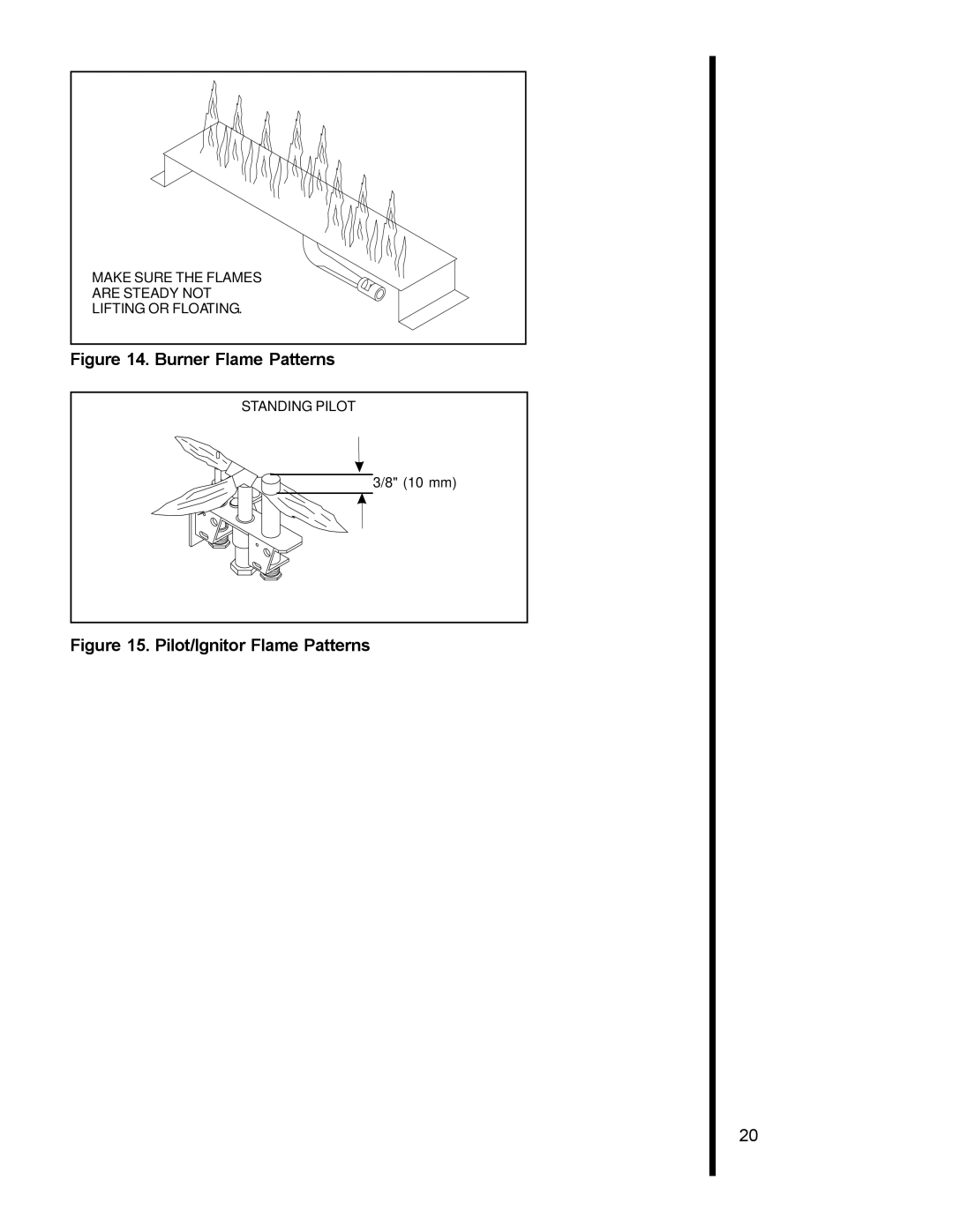
MAKE SURE THE FLAMES
ARE
STEADY—NOT
LIFTING OR FLOATING.
Figure 14. Burner Flame Patterns
STANDING PILOT
3/8" (10 mm)
Figure 15. Pilot/Ignitor Flame Patterns
20
Page 22
Page 24
Page 23
Image 23
Page 22
Page 24
Contents
Heat-N-Glo Fireplace
Safety and Warning Information
Safety and Warning Information
Table of Contents
Codes
Approvals and Codes
Getting Started
Venting and Installation
Diagram of the AT-GRAND
Horizontal Venting
Installing the Insert Step Vent System
Vent System Installation Precautions
Vent System Approvals
Flex pipes to the starting collars on the unit with
Connecting the Vent Pipe
Minimum Height from Roof to Lowest Discharge Opening
Page
Inlet AIR
Gas Controls Systems
Standing Pilot Ignition System
Gas Supply Line
Step Gas Supply Line
Appliance Requirements
Step Gas Pressure Requirements Wiring Fireplace
Pressure Natural Gas Propane
Remote Wall Switch
Optional Accessories
Placing the Ember Material
Step Installing Logs Ember Material
Positioning the Logs
Save the log instructions with this manual
Glass Assembly
Step Installing Trim Surrounds
Mantel
Double-check for gas leaks
Step Before Lighting Appliance After Installation
Review safety warnings and cautions
Double-check for faulty components
Maintaining and Servicing Your Appliance
Appliance Maintenance
Burner Flame Patterns
Standing Pilot Only
Replacement Parts Accessories
Standing Pilot
R T PA R T PAR T N U M B E R S C R IP T IO N
Top
Page
Image
Contents