|
|
|
|
|
|
|
|
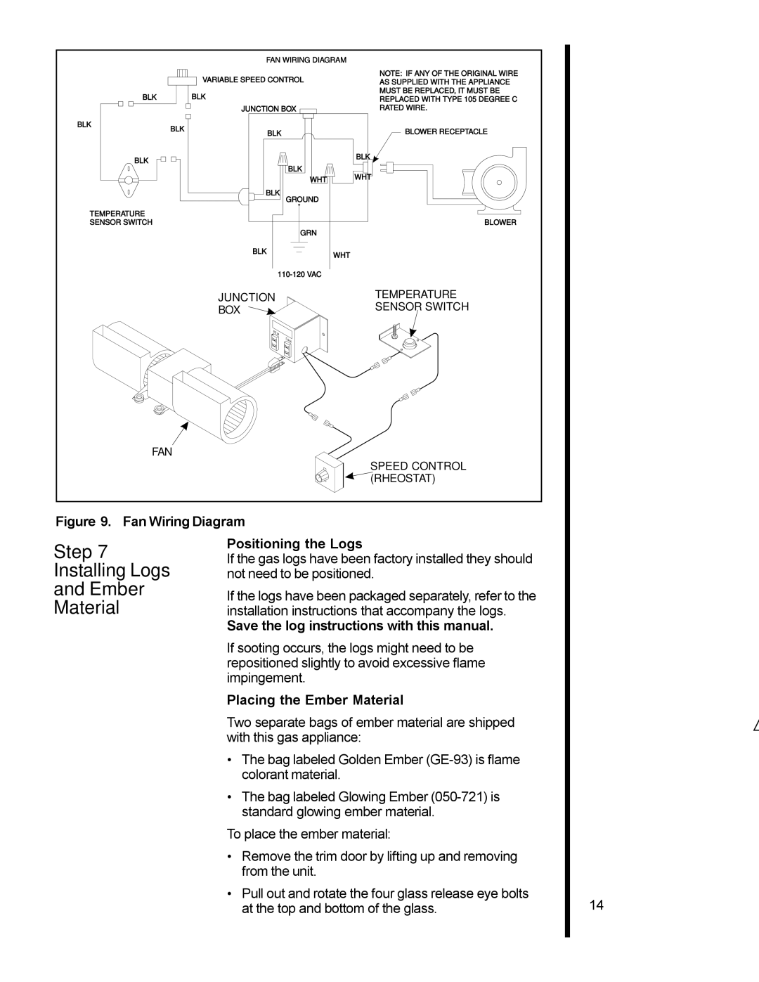
| FAN WIRING DIAGRAM |
|
|
|
|
|
|
|
|
| VARIABLE SPEED CONTROL |
|
|
|
|
|
|
|
|
| |
|
|
|
|
| |||||
BLK |
|
|
|
|
|
|
|
| BLK |
|
| JUNCTION BOX |
|
BLK | BLK |
|
|
| BLK |
| |
|
|
| |
BLK |
| BLK |
|
|
|
| |
|
| WHT |
|
|
| BLK |
|
|
| GROUND |
|
TEMPERATURE |
|
|
|
SENSOR SWITCH |
|
|
|
|
| GRN |
|
|
| BLK | WHT |
|
|
| |
|
|
|
NOTE: IF ANY OF THE ORIGINAL WIRE AS SUPPLIED WITH THE APPLIANCE MUST BE REPLACED, IT MUST BE REPLACED WITH TYPE 105 DEGREE C RATED WIRE.
BLOWER RECEPTACLE
BLK ![]()
WHT
BLOWER
JUNCTION | TEMPERATURE |
BOX | SENSOR SWITCH |
|
FAN
SPEED CONTROL (RHEOSTAT)
Figure 9. Fan Wiring Diagram
Step 7
Installing Logs
and Ember
Material
Positioning the Logs
If the gas logs have been factory installed they should not need to be positioned.
If the logs have been packaged separately, refer to the installation instructions that accompany the logs.
Save the log instructions with this manual.
If sooting occurs, the logs might need to be repositioned slightly to avoid excessive flame impingement.
Placing the Ember Material
Two separate bags of ember material are shipped with this gas appliance:
•The bag labeled Golden Ember
•The bag labeled Glowing Ember
To place the ember material:
•Remove the trim door by lifting up and removing from the unit.
•Pull out and rotate the four glass release eye bolts at the top and bottom of the glass.
14