3.Run the low voltage lead wires up the back of the right side of the surround and secure them with the three wire ties found there.
4.Remove and retain the four surround attachment screws at the corners of the face of the unit. See Figure 12.
5.Slide the surround against the face of the unit, aligning the holes in upper and lower, right and left corners and secure the surround to the unit with the attachment screws.
NOTE: PLACE THE THREE INSULATION PIECES INTO THE CAVITIES AT THE BACK OF THE SURROUND BEFORE POSITIONING THE INSERT INTO THE
MANTEL
12” MAX.
![]() 12” MAX.
12” MAX.
17
TOP OF UNIT
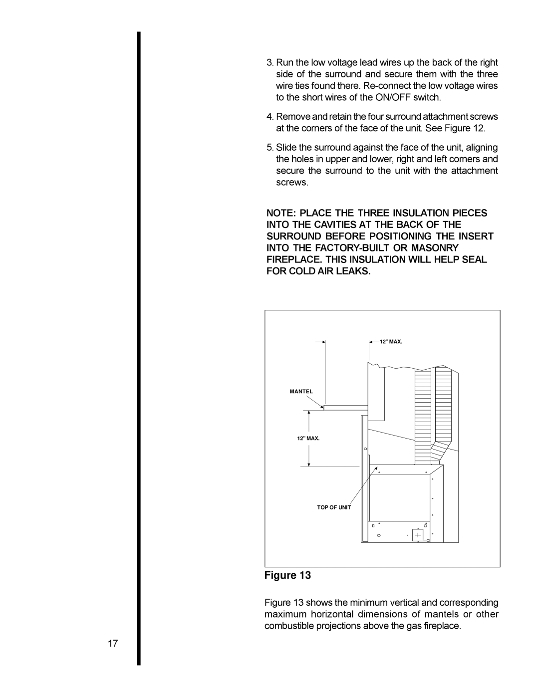
Figure 13