Manuals
/
Heat & Glo LifeStyle
/
Household Appliance
/
Indoor Fireplace
Heat & Glo LifeStyle
BE-41C, BE-41IPIC, BE-41LPC, BE-41IPILPC
owner manual
Either cobrahead or SIT
Models:
BE-41C
BE-41LPC
BE-41IPILPC
BE-41IPIC
1
16
69
69
Download
69 pages
5.73 Kb
13
14
15
16
17
18
19
20
Troubleshooting
Install
FAQ
Vent Information and Diagrams
Wiring Requirements
Warranty
Maintenance
Appliance Setup
Fixed Glass Assembly
Air Shutter Setting
Page 16
Image 16
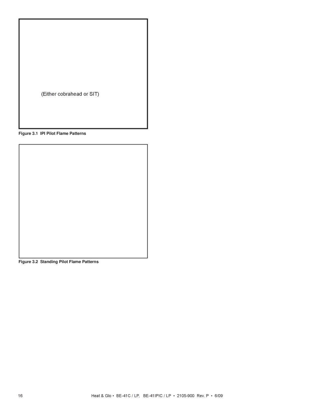
(Either cobrahead or SIT)
Figure 3.1 IPI Pilot Flame Patterns
Figure 3.2 Standing Pilot Flame Patterns
16
Heat & Glo •
BE-41C /
LP,
BE-41IPIC /
LP •
2105-900
Rev. P • 6/09
Page 15
Page 17
Page 16
Image 16
Page 15
Page 17
Contents
What to do if you smell gas
Hot glass will cause burns
Congratulations
Homeowner Reference Information
Table of Contents
User Guide
Appliance Setup
Troubleshooting
Finishing
Reference Materials
Limited Lifetime Warranty
Limited Lifetime Warranty
Listing and Code Approvals
Installation of Carbon Monoxide Detectors
Requirements for the Commonwealth of Massachusetts
Operating Instructions User Guide
Gas Fireplace Safety
Your Fireplace
Fixed Glass Assembly
Remote Controls, Wall Controls and Wall Switches
Fan Kit optional
Clear Space
Turn off all electric power to the appliance
On position. The ON/OFF switch may
Lighting Instructions IPI
Final inspection by
For Your Safety Read Before Lighting Lighting Instructions
Lighting Instructions Standing Pilot
Frequently Asked Questions
After Fireplace is Lit
Maintenance and Service
Maintenance Tasks-Homeowner
Glass Cleaning
Remote Control
Maintenance Tasks-Qualified Service Technician
Gasket Seal and Glass Assembly Inspection
Venting
Logs
Either cobrahead or SIT
Getting Started
Typical Appliance System
Design and Installation Considerations
Tools and Supplies Needed
Inspect Appliance and Components
Any such action may cause a fire hazard
Framing and Clearances
Selecting Appliance Location
Constructing the Appliance Chase
Clearances
Combustible Mantels
Mantel and Wall Projections
Combustible Mantel Legs or Wall Projections
Termination Locations
Vent Termination Minimum Clearances
Covered Alcove Applications
Vent Information and Diagrams
Approved Pipe
Vent Table Key
Use of Elbows
Vent Diagrams Top Vent Horizontal Termination
One Elbow
Two Elbows
V1 Minimum H1 Maximum
Top Vent Horizontal Termination Three Elbows
Min Max
Break Here
Top Vent Vertical Termination
Maximum + V 2 Min
Top Vent Vertical Termination Three Elbows
H1 + H2 V1 + V2 Minimum H1 + H2 Maximum
Heat & Glo BE-41C / LP, BE-41IPIC / LP 2105-900 Rev. P 6/09
H1 Maximum V1 Minimum H1 + H2 Maximum
Rear Vent Horizontal Termination Two Elbows
H1 Maximum V1 Minimum H2+ H3 H1+ H2+ H3 Max
Rear Vent Vertical Termination One Elbow
H1 + H2 Maximum V1 Minimum
Rear Vent Vertical Termination Three Elbows
V1 Minimum H1 + H2 + H3
Vent Clearances and Framing
Pipe Clearances to Combustibles
Wall Penetration Framing
Combustible Wall Penetration
Install the Ceiling Firestop
Pipe DVP SLP
Flat Ceiling Installation
Install Attic Insulation Shield
Vaulted Ceiling Installation
Appliance Preparation
Top Vent
Rear Vent
Cut the metal retaining band and fold the sides out
Installing the Non-combustible Board
Securing and Leveling the Appliance
Installing Vent Pipe DVP and SLP Pipe
Attach Vent to the Firebox Assembly
Assemble Vent Sections DVP Pipe Only
Assemble Pipe Sections
Assemble Vent Sections SLP Pipe Only
Assemble Slip Sections
Secure the Vent Sections
Disassemble Vent Sections
Install Decorative Ceiling Components SLP only
Install Metal Roof Flashing
Assemble and Install Storm Collar
Install Decorative Wall Components SLP only
Install Vertical Termination Cap
Heat Shield Requirements for Horizontal Termination
Ansi Z223.1 and CAN/CGA-B149 installation codes
Install Horizontal Termination Cap DVP and SLP Pipe
Refer to of this manual
Gas Information
Fuel Conversion
Gas Pressure
Gas Connection
Wiring Requirements
IntelliFire Ignition System Wiring
Standing Pilot Ignition System Wiring
Optional Accessories Requirements
Electrical Service and Repair
IntelliFire Pilot Ignition IPI Wiring Diagram
Junction Box Installation
Wall Switch Installation for Fan Optional
Finishing
Facing Material
Doors
Finish Door FIT Material See Maximum Thickness
Appliance Setup
LOG Assembly LOGS-6000BE
Install the Log Assembly
Log Placement Tabs
Install Trim and/or Surround
Air Shutter Setting
Air Shutter Settings
Burner
Symptom Possible Causes Corrective Action
Troubleshooting
Standing Pilot Ignition System
Troubleshooting
Symptom Possible Cause Corrective Action
IntelliFire Ignition System
Ues to spark, and main
Reference Materials
Appliance Dimension Diagram
Location Inches Millimeters
Vent Components Diagrams
DVP vent components
Horizontal Termination Cap
DVP vent components
787 mm 13-1/4 367 mm 24-5/8 625 mm 27-1/2 127 mm
Roof Flashing Multi-pak 13-3/4 11-7/8 349 mm
302 mm
13-3/4 13-7/8 352 mm 349 mm
DVP-TVHW
DVP-HRC-SS DVP-HRC-ZC-SS Horizontal Termination CAP
165 mm 222 mm 168 mm
Elbow Effective Height Length
Horizontal Pipe Support
2 in mm 152 mm 8 in mm 251 mm SLP-90ST 90 Elbow
Cathedral Ceiling
Snorkel
Support Box-Black Termination Cap
Ceiling Firestop
Contact Information
Top
Page
Image
Contents