Heat & Glo LifeStyle BE-41C B. Vent Components Diagrams continued, Slp-Snkd, Slp-Ccs-Bk, Slp-Tvhw

Models: BE-41C BE-41LPC BE-41IPILPC BE-41IPIC

1 69
Download 69 pages 5.73 Kb
Page 68
Image 68
SLP-SNKD

B. Vent Components Diagrams (continued)

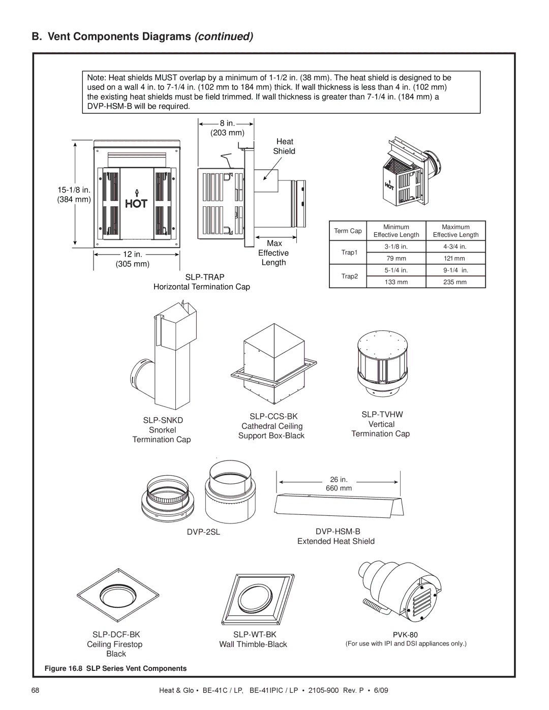
Note: Heat shields MUST overlap by a minimum of 1-1/2 in. (38 mm). The heat shield is designed to be used on a wall 4 in. to 7-1/4 in. (102 mm to 184 mm) thick. If wall thickness is less than 4 in. (102 mm) the existing heat shields must be field trimmed. If wall thickness is greater than 7-1/4 in. (184 mm) a DVP-HSM-B will be required.

SLP-CCS-BK 8 in.SLP-TVHW (203 mm)

Heat

Shield

15-1/8 in.

(384 mm)


Max

12 in.

Effective

(305 mm)

Length

SLP-TRAP

Horizontal Termination Cap

Term Cap

Minimum

Maximum

Effective Length

Effective Length


Trap1

3-1/8 in.

4-3/4 in.

79 mm

121 mm


Trap2

5-1/4 in.

9-1/4 in.

133 mm

235 mm


SLP-SNKD

SLP-CCS-BK

SLP-TVHW

Cathedral Ceiling

Vertical

Snorkel

Support Box-Black

Termination Cap

Termination Cap


26 in.


660 mm

DVP-2SL

DVP-HSM-B


Extended Heat Shield


SLP-DCF-BK

SLP-WT-BK

PVK-80


Ceiling Firestop

Wall Thimble-Black

(For use with IPI and DSI appliances only.)


Black


Figure 16.8 SLP Series Vent Components


68

Heat & Glo • BE-41C / LP, BE-41IPIC / LP • 2105-900 Rev. P • 6/09

Page 68
Image 68
Heat & Glo LifeStyle BE-41C B. Vent Components Diagrams continued, Slp-Snkd, Slp-Ccs-Bk, Slp-Tvhw, Cathedral Ceiling