Heat & Glo LifeStyle BE-41LPC, BE-41C, BE-41IPIC B. Vent Components Diagrams continued, Fire Risk

Models: BE-41C BE-41LPC BE-41IPILPC BE-41IPIC

1 69
Download 69 pages 5.73 Kb
Page 66
Image 66
DVP-HRC-SS

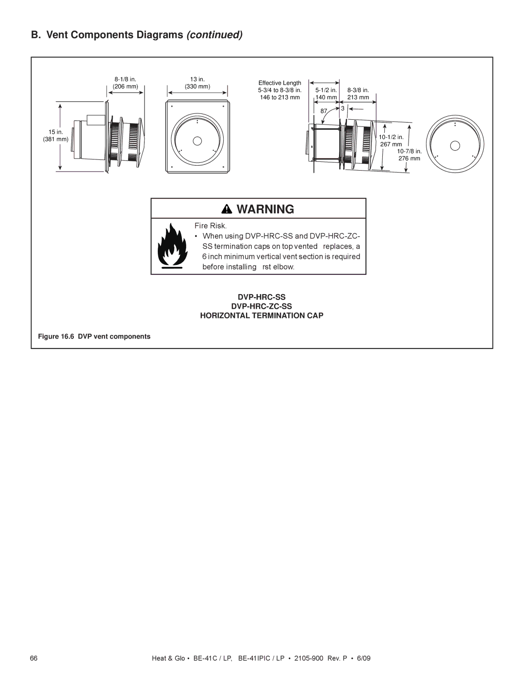
B. Vent Components Diagrams (continued)

8-1/8 in.

(206 mm)

15in.

(381 mm)

13 in.

Effective Length


(330 mm)


5-1/2 in.


8-3/8 in.

5-3/4 to 8-3/8 in.


146 to 213 mm


140 mm


213 mm


87°


10-1/2 in.

267 mm

10-7/8 in.

276 mm

HORIZONTAL TERMINATION CAP WARNING

Fire Risk.

When using DVP-HRC-SS and DVP-HRC-ZC- SS termination caps on top vented fireplaces, a

6 inch minimum vertical vent section is required before installing first elbow.

DVP-HRC-SS

DVP-HRC-ZC-SS

HORIZONTAL TERMINATION CAP

Figure 16.6 DVP vent components

66

Heat & Glo • BE-41C / LP, BE-41IPIC / LP • 2105-900 Rev. P • 6/09

Page 66
Image 66
Heat & Glo LifeStyle BE-41LPC, BE-41C, BE-41IPIC B. Vent Components Diagrams continued, Fire Risk, Dvp-Hrc-Ss Dvp-Hrc-Zc-Ss