15 Troubleshooting
With proper installation, operation, and maintenance your gas appliance will provide years of
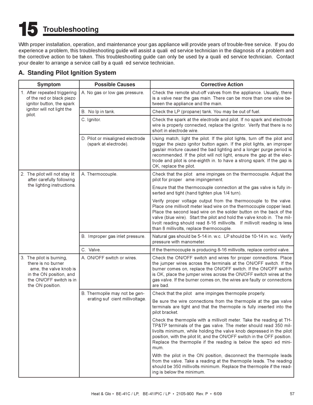
A. Standing Pilot Ignition System
| Symptom | Possible Causes | Corrective Action |
1. After repeated triggering | A. No gas or low gas pressure. | Check the remote | |
| of the red or black piezo |
| is a valve near the gas main. There can be more than one valve be- |
| ignitor button, the spark |
| tween the appliance and the main. |
| ignitor will not light the |
|
|
| B. No lp in tank. | Check the LP (propane) tank. You may be out of fuel. | |
| pilot. | ||
| C. Ignitor. | Check the spark at the electrode and pilot. If no spark and electrode | |
|
| ||
|
|
| wire is properly connected, replace the ignitor. Verify that there is no |
|
|
| short in electrode wire. |
|
| D. Pilot or misaligned electrode | Using match, light the pilot. If the pilot lights, turn off the pilot and |
|
| (spark at electrode). | trigger the piezo ignitor button again. If the pilot lights, an improper |
|
|
| gas/air mixture caused the bad lighting and a longer purge period is |
|
|
| recommended. If the pilot will not light, ensure the gap at the elec- |
|
|
| trode and pilot is |
|
|
| OK, replace the pilot. |
2. | The pilot will not stay lit | A. Thermocouple. | Check that the pilot flame impinges on the thermocouple. Adjust the |
| after carefully following |
| pilot for proper flame impingement. |
| the lighting instructions. |
| Ensure that the thermocouple connection at the gas valve is fully in- |
|
|
| |
|
|
| serted and tight (hand tighten plus 1/4 turn). |
|
|
| Verify proper voltage output from the thermocouple to the valve. |
|
|
| Place one millivolt meter lead wire on the thermocouple copper lead. |
|
|
| Place the second lead wire on the solder button on the back of the |
|
|
| valve (blue wire). Start the pilot and hold the valve knob in. The mil- |
|
|
| livolt reading should read |
|
|
| than 8 millivolts, replace thermocouple. |
|
| B. Improper gas inlet pressure. | Natural gas should be |
|
|
| pressure with manometer. |
|
| C. Valve. | If the thermocouple is producing |
|
|
|
|
3. | The pilot is burning, | A. ON/OFF switch or wires. | Check the ON/OFF switch and wires for proper connections. Place |
| there is no burner |
| the jumper wires across the terminals at the ON/OFF switch. If the |
| flame, the valve knob is |
| burner comes on, replace the ON/OFF switch. If the ON/OFF switch |
| in the ON position, and |
| is OK, place the jumper wires across the ON/OFF switch wires at the |
| the ON/OFF switch is in |
| gas valve. If the burner comes on, the wires are faulty or connections |
| the ON position. |
| are bad. |
|
| B. Thermopile may not be gen- | Check that the pilot flame impinges thermopile properly. |
|
| erating sufficient millivoltage. | Be sure the wire connections from the thermopile at the gas valve |
|
|
| |
|
|
| terminals are tight and that the thermopile is fully inserted into the |
|
|
| pilot bracket. |
|
|
| Check the thermopile with a millivolt meter. Take the reading at TH- |
|
|
| TP&TP terminals of the gas valve. The meter should read 350 mil- |
|
|
| livolts minimum, while holding the valve knob depressed in the pilot |
|
|
| position, with the pilot lit, and the ON/OFF switch in the OFF position. |
|
|
| Replace the thermopile if the reading is below the specified mini- |
|
|
| mum. |
|
|
| With the pilot in the ON position, disconnect the thermopile leads |
|
|
| from the valve. Take a reading at the thermopile leads. The reading |
|
|
| should be 350 millivolts minimum. Replace the thermopile if the read- |
|
|
| ing is below the minimum. |
|
|
|
|
Heat & Glo • | 57 |