8Finishing
A. Mantel Projections
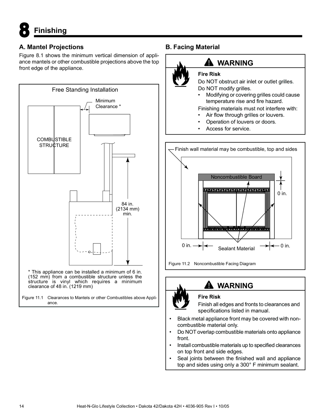
Figure 8.1 shows the minimum vertical dimension of appli- ance mantels or other combustible projections above the top front edge of the appliance.
Free Standing Installation
Minimum
Clearance *
COMBUSTIBLE
STRUCTURE
84 in.
(2134 mm)
min.
*This appliance can be installed a minimum of 6 in. (152 mm) from a combustible structure unless the structure is vinyl which requires a minimum clearance of 48 in. (1219 mm)
Figure 11.1 Clearances to Mantels or other Combustibles above Appli- ance.
B. Facing Material
![]() WARNING
WARNING
Fire Risk
Do NOT obstruct air inlet or outlet grilles.
Do NOT modify grilles.
•Modifying or covering grilles could cause temperature rise and fi re hazard.
Finishing materials must not interfere with:
•Air fl ow through grilles or louvers.
•Operation of louvers or doors.
•Access for service.
Finish wall material may be combustible, top and sides | ||
| Noncombustible Board |
|
|
| 0 in. |
0 in. | Sealant Material | 0 in. |
|
| |
Figure 11.2 Noncombustible Facing Diagram |
| |
![]() WARNING
WARNING
Fire Risk
Finish all edges and fronts to clearances and specifi cations listed in manual.
•Black metal appliance front may be covered with non- combustible material only.
•Do NOT overlap combustible materials onto appliance front.
•Install combustible materials up to specified clearances on top front and side edges.
•Seal joints between the fi nished wall and appliance top and sides using only a 300° F minimum sealant.
14 |
