8 Vent Clearances and Framing
A. Pipe Clearances to Combustibles
WARNING! Risk of Fire! Maintain air space clearance to vent. DO NOT pack insulation or other combustibles:
•Between ceiling firestops
•Between wall shield firestops
•Around vent system
Failure to keep insulation or other material away from vent pipe may cause over heating and fire.
Note: Heat shields MUST overlap by a minimum of
DVP heat shield - designed to be used on a wall 4 in. to
,f wall thickness is less than 4 in. the e[isting heat shields must be field trimmed. ,f wall thickness is greater than
SLP heat shield - designed to be used on a wall
,f wall thickness is less than
B. Continue Adding Vent Components
WARNING! Risk of Fire! Installation of this appliance may require the use of heat shield
•The heat shield is required above the first elbow if the clearance to combustible surface above is between three (3) and four (4) inches. A shield is not required for clearances greater than four inches. See Figure 8.2.
COMBUSTIBLE
SURFACE
HEAT | 3 in. MIN. |
SHIELD | (76 mm) |
(Required for clearances |
|
between 3 and 4 inches.) |
|
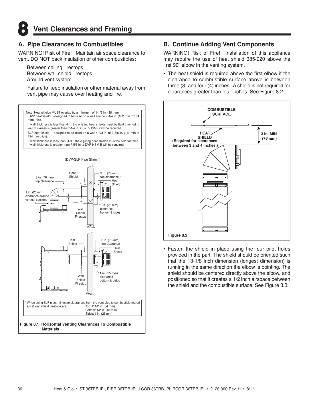
3 in. (76 mm) top clearance
1 in. (25 mm) clearance around ![]() vertical sections
vertical sections ![]()
![]()
![]()
![]()
![]()
| |
Heat | 3 in. (76 mm) |
Shield | top clearance * |
| Heat |
| Shield |
| 1 in. (25 mm) |
Wall | clearance |
Shield | bottom & sides |
Firestop |
|
| WALL |
Figure 8.2
Heat
Shield
Wall
Shield
Firestop
WALL
3 in. (76 mm) top clearance *
Heat
Shield
![]() 1 in. (25 mm) clearance bottom & sides
1 in. (25 mm) clearance bottom & sides
•Fasten the shield in place using the four pilot holes provided in the part. The shield should be oriented such that the
* When using SLP pipe, minimum clearances from the vent pipe to combustible materi-
als at wall shield firestops are:Top:
Figure 8.1 Horizontal Venting Clearances To Combustible Materials
36 | Heat & Glo • |