User Manual |
| Heat Controller, Inc. |
|
|
|
•Auto Fan Only (default): During the scheduled Programmed Demand Reduction time (section 5.6.5.5.4), only auto fan mode is allowed.
•Allow Continuous Fan: During the scheduled Programmed Demand Reduction time (section 5.6.5.5.4), the fan will operate normally.
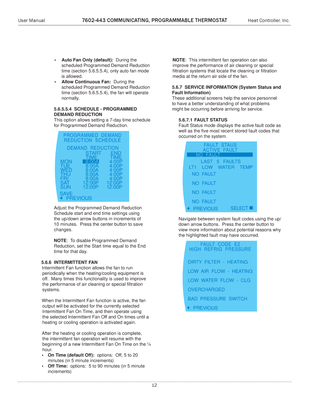
5.6.5.5.4SCHEDULE - PROGRAMMED DEMAND REDUCTION
This option allows setting a
PROGRAMMED DEMAND
REDUCTION SCHEDULE
DEMAND REDUCTION
| START | END | |
| TIME | TIME | |
MON | 8:00A |
| 4:00P |
TUE | 8:00A |
| 4:00P |
WED | 8:00A | 4:00P | |
THU | 8:00A | 4:00P | |
FRI | 8:00A | 4:00P | |
SAT | 12:00P | 12:00P | |
SUN | 12:00P | 12:00P | |
SAVE
PREVIOUS
Adjust the Programmed Demand Reduction Schedule start and end time settings using the up/down arrow buttons in increments of 10 minutes. Press the center button to save changes.
NOTE: To disable Programmed Demand Reduction, set the Start time equal to the End time for that day.
5.6.6 INTERMITTENT FAN
Intermittent Fan function allows the fan to run periodically when the heating/cooling equipment is off. Many times this functionality is used to improve the performance of air cleaning or special filtration systems.
When the Intermittent Fan function is active, the fan output will be activated for the currently selected Intermittent Fan On Time, and then operate using the selected Intermittent Fan Off and On times until a heating or cooling operation is activated again.
After the heating or cooling operation is complete, the intermittent fan operation will resume with the beginning of a new Intermittent Fan On Time on the ¼ hour.
•On Time (default Off): options: Off, 5 to 20 minutes (in 5 minute increments)
•Off Time: options: 5 to 90 minutes (in 5 minute increments)
NOTE: This intermittent fan operation can also improve the performance of air cleaning or special filtration systems that locate the cleaning or filtration media at the return air side of the fan.
5.6.7SERVICE INFORMATION (System Status and Fault Information)
These additional screens help the service personnel to have a better understanding of what problems might be occurring before arriving for service.
5.6.7.1FAULT STATUS
Fault Status mode displays the active fault code as well as the five most recent stored fault codes that occurred on the system.
FAULT STAUS
ACTIVE FAULT
NO FAULT
LAST 5 FAULTS
NO DEMAND REDUCTION
LT1 LOW WATER TEMP
NO FAULT
NO FAULT
NO FAULT
NO FAULT
PREVIOUS SELECT 
Navigate between system fault codes using the up/ down arrow buttons. Press the center button to view more information about potential reasons why the highlighted fault may have occurred.
FAULT CODE E2
HIGH REFRIG PRESSURE
DIRTY FILTER - HEATING
NO DEMAND REDUCTION
LOW AIR FLOW - HEATING
LOW WATER FLOW - CLG
OVERCHARGED
BAD PRESSURE SWITCH
PREVIOUS
12