4 Getting Started | Installer Guide |
|
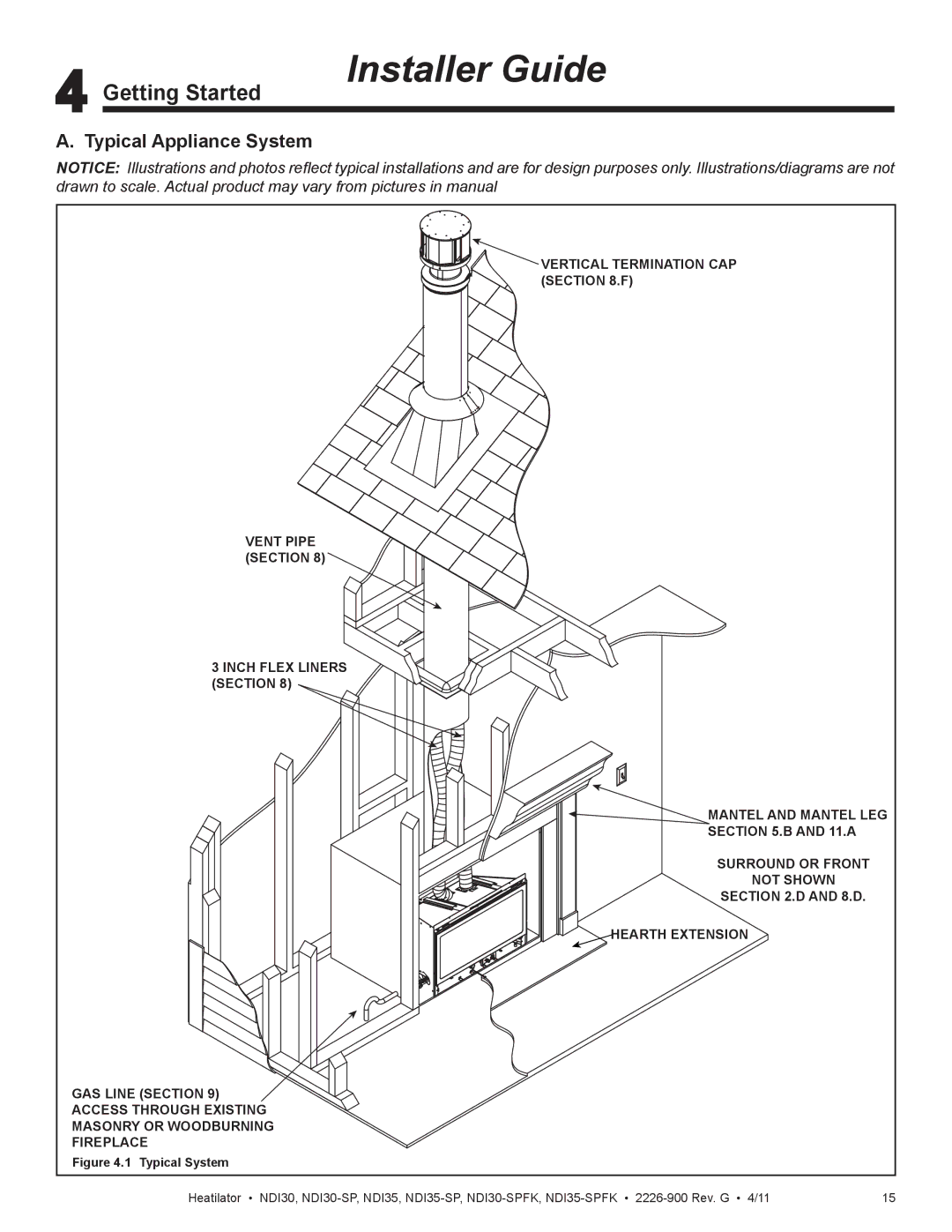
A. Typical Appliance System
NOTICE: Illustrations and photos reflect typical installations and are for design purposes only. Illustrations/diagrams are not drawn to scale. Actual product may vary from pictures in manual
![]()
![]()
![]()
![]() VERTICAL TERMINATION CAP
VERTICAL TERMINATION CAP ![]()
![]()
![]()
![]()
![]()
![]()
![]() (SECTION 8.F)
(SECTION 8.F)
VENT PIPE (SECTION 8)
3 INCH FLEX LINERS (SECTION 8)
MANTEL AND MANTEL LEG
SECTION 5.B AND 11.A
SURROUND OR FRONT
NOT SHOWN
SECTION 2.D AND 8.D.
![]()
![]()
![]()
![]()
![]()
![]()
![]() HEARTH EXTENSION
HEARTH EXTENSION
GAS LINE (SECTION 9)
ACCESS THROUGH EXISTING
MASONRY OR WOODBURNING
FIREPLACE
Figure 4.1 Typical System
Heatilator • NDI30, | 15 |