8 Installing Vent Pipe and Appliance
A. Vent Limits
The abbreviations listed in this vent table key are used in the vent diagrams.
B. Venting Components
CAUTION! Risk of Cuts/Abrasions/Flying Debris. Wear protective gloves and safety glasses during instal- lation. Sheet metal edges are sharp.
Description
Minimum Vertical Run Length 10 ft.
Maximum Vertical Run Length 50 ft.
Horizontal venting is NOT allowed.
Vertical terminations are measured to top of chimney.
This appliance is listed for use with
WARNING! Risk of Fire/Explosion/Asphyxiation! Do NOT connect this gas appliance to a chimney flue serving a separate solid fuel or gas burning appliance.
•May impair safe operation of this appliance or other appliances connected to the flue.
•Vent this appliance directly outside.
•Use separate vent system for this appliance.
CAUTION! ALL vent specifications MUST be followed. This product is tested and listed to these specifications. Appliance performance will suffer if specifications are not followed.
The vertical vent termination system installed on this model includes:
•Flexible vent pipe for exhaust air (included with vent kit).
•One length of
•One
•One vertical termination cap (included with vent kit).
C. Connecting Vent Pipe
Reference instructions in the termination kit.
•Install the
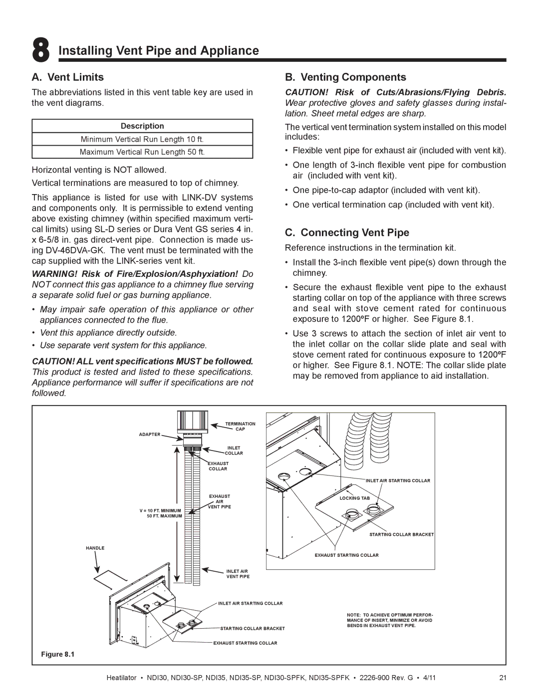
•Secure the exhaust flexible vent pipe to the exhaust starting collar on top of the appliance with three screws and seal with stove cement rated for continuous exposure to 1200ºF or higher. See Figure 8.1.
•Use 3 screws to attach the section of inlet air vent to the inlet collar on the collar slide plate and seal with stove cement rated for continuous exposure to 1200ºF or higher. See Figure 8.1. NOTE: The collar slide plate may be removed from appliance to aid installation.
| TERMINATION |
|
ADAPTER | CAP |
|
|
| |
| INLET |
|
| COLLAR |
|
| EXHAUST |
|
| COLLAR |
|
|
| INLET AIR STARTING COLLAR |
| EXHAUST | LOCKING TAB |
| AIR | |
|
| |
V = 10 FT. MINIMUM | VENT PIPE |
|
|
| |
50 FT. MAXIMUM |
|
|
|
| STARTING COLLAR BRACKET |
HANDLE |
|
|
|
| EXHAUST STARTING COLLAR |
| INLET AIR |
|
| VENT PIPE |
|
| INLET AIR STARTING COLLAR |
|
|
| NOTE: TO ACHIEVE OPTIMUM PERFOR- |
|
| MANCE OF INSERT, MINIMIZE OR AVOID |
| STARTING COLLAR BRACKET | BENDS IN EXHAUST VENT PIPE. |
|
| |
| EXHAUST STARTING COLLAR |
|
Figure 8.1 |
|
|
Heatilator • NDI30, | 21 |