10 Electrical Information
A. Wiring Requirements
NOTICE: This appliance must be electrically wired and grounded in accordance with local codes or, in the absence of local codes, with National Electric Code ANSI/NFPA
Code CSA C22.1.
•This appliance comes standard with a 120 VAC cord assembly which has a female plug in to accommodate all control options and accessories. See Figure 10.5. This is required for use of optional accessories (standing pilot ignition) or proper operation of the appliance (IntelliFire Ignition). An outlet box may be installed in a bottom back corner of the existing solid fuel masonry or factory built fi replace to plug in the cord assembly, or the supplied power cord may be routed out onto the hearth to a nearby outlet.
•A 120 VAC circuit for this product must be protected with
•Low voltage and 120 VAC voltage cannot be shared within the same wall box.
WARNING! Risk of Shock or Explosion! DO NOT wire 120V to the valve or to the appliance wall switch. Incor- rect wiring will damage controls.
•Determine if the appliance uses an Intellifire ignition system or standing pilot ignition system.
•Open the control access panel or remove the decorative front.
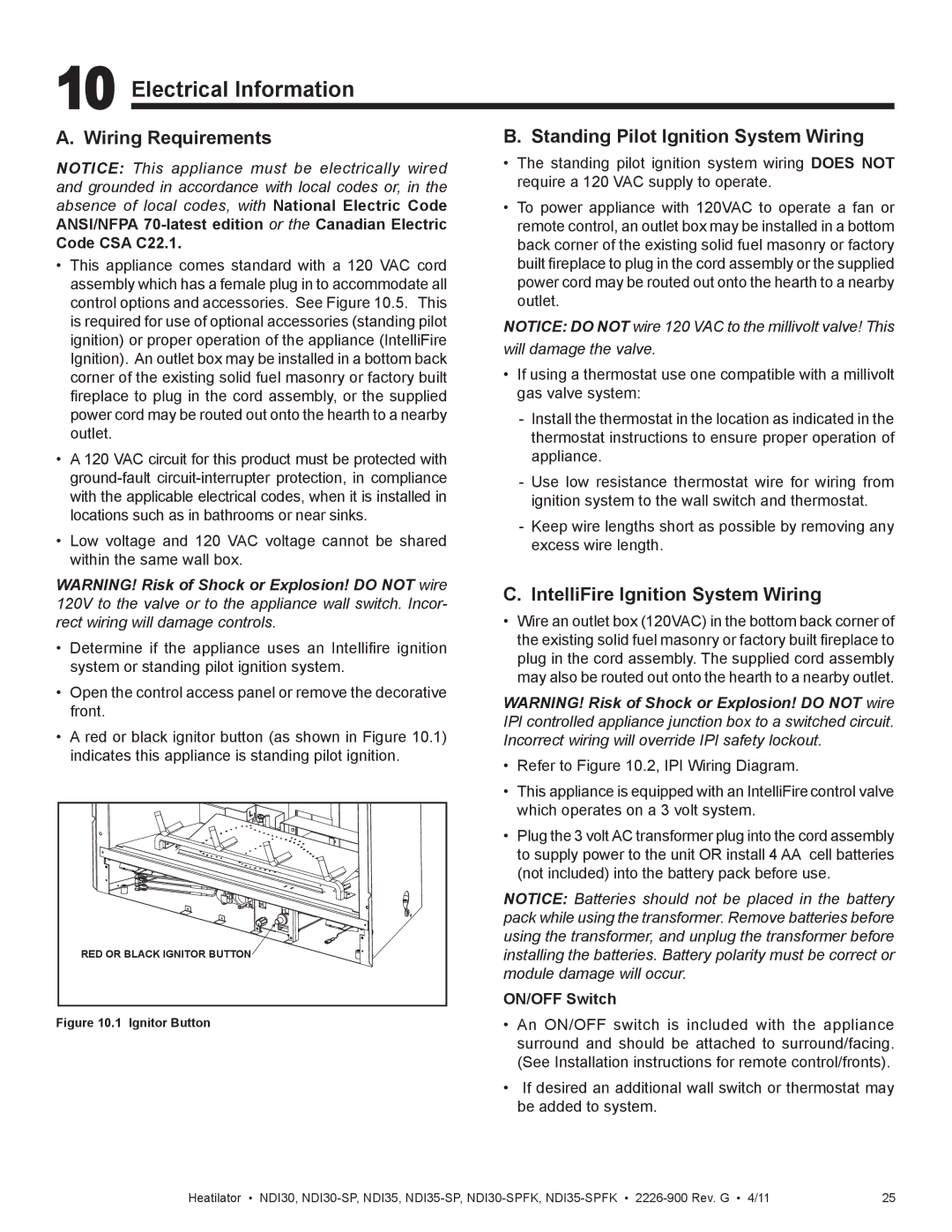
•A red or black ignitor button (as shown in Figure 10.1) indicates this appliance is standing pilot ignition.
RED OR BLACK IGNITOR BUTTON |
Figure 10.1 Ignitor Button
B. Standing Pilot Ignition System Wiring
•The standing pilot ignition system wiring DOES NOT require a 120 VAC supply to operate.
•To power appliance with 120VAC to operate a fan or remote control, an outlet box may be installed in a bottom back corner of the existing solid fuel masonry or factory built fireplace to plug in the cord assembly or the supplied power cord may be routed out onto the hearth to a nearby outlet.
NOTICE: DO NOT wire 120 VAC to the millivolt valve! This
will damage the valve.
•If using a thermostat use one compatible with a millivolt gas valve system:
-Install the thermostat in the location as indicated in the thermostat instructions to ensure proper operation of appliance.
-Use low resistance thermostat wire for wiring from ignition system to the wall switch and thermostat.
-Keep wire lengths short as possible by removing any excess wire length.
C. IntelliFire Ignition System Wiring
•Wire an outlet box (120VAC) in the bottom back corner of the existing solid fuel masonry or factory built fireplace to plug in the cord assembly. The supplied cord assembly may also be routed out onto the hearth to a nearby outlet.
WARNING! Risk of Shock or Explosion! DO NOT wire IPI controlled appliance junction box to a switched circuit. Incorrect wiring will override IPI safety lockout.
•Refer to Figure 10.2, IPI Wiring Diagram.
•This appliance is equipped with an IntelliFirecontrol valve which operates on a 3 volt system.
•Plug the 3 volt AC transformer plug into the cord assembly to supply power to the unit OR install 4 AA cell batteries (not included) into the battery pack before use.
NOTICE: Batteries should not be placed in the battery pack while using the transformer. Remove batteries before using the transformer, and unplug the transformer before installing the batteries. Battery polarity must be correct or module damage will occur.
ON/OFF Switch
•An ON/OFF switch is included with the appliance surround and should be attached to surround/facing. (See Installation instructions for remote control/fronts).
•If desired an additional wall switch or thermostat may be added to system.
Heatilator • NDI30, | 25 |