Models NNXT4236I, NNXT4236IL NNXT3933I, NNXT3933IL
What to do if you smell gas
Owner’s Manual
Please retain this owner’s manual for future reference
Read this manual before installing or operating this appliance
A. Congratulations
Homeowner Reference Information
Safety Alert Key
Table of Contents
Installer Guide
User Guide
Removing Fixed Glass Assembly
Remove Screen Package Assembly
Clean the Appliance
Accessories
Hearth & Home Technologies Inc LIMITED LIFETIME WARRANTY
B. Limited Lifetime Warranty
WARRANTY COVERAGE
WARRANTY PERIOD
WARRANTY CONDITIONS
B. Limited Lifetime Warranty continued
WARRANTY EXCLUSIONS
This warranty is void if
1 Listing and Code Approvals
D. High Altitude Installations
A. Appliance Certification
B. Glass Specifications
Installation of Carbon Monoxide Detectors
H. Requirements for the Commonwealth of Massachusetts
Approved Carbon Monoxide Detectors
Signage
User Guide
A. Gas Fireplace Safety
2 Operating Instructions
B. Your Fireplace
G. Remote Controls, Wall Controls and Wall Switches
F. Fixed Glass Assembly
C. Fan Kit optional
D. Clear Space
I. Control Module Operation
H. IPI Battery Tray/Battery Installation
J. Before Lighting Fireplace
5. Module Reset
Final inspection by
K. Lighting Instructions IPI
FOR YOUR SAFETY READ BEFORE LIGHTING
LIGHTING INSTRUCTIONS IPI
L. After Fireplace is Lit
M. Frequently Asked Questions
Initial Break-in Procedure
NOTICE! Open windows for air circulation during fireplace break-in
A. Maintenance Tasks-Homeowner
3 Maintenance and Service
Glass Cleaning
Remote Control
Gasket Seal and Glass Assembly Inspection
B. Maintenance Tasks-Qualified Service Technician
Logs
Firebox
Installer Guide
Getting Started
A. Typical Appliance System
B. Design and Installation Considerations
C. Tools and Supplies Needed
D. Inspect Appliance and Components
A. Select Appliance Location
5 Framing and Clearances
Model
Figure 5.1 Appliance Locations
B. Construct the Appliance Chase
C. Clearances
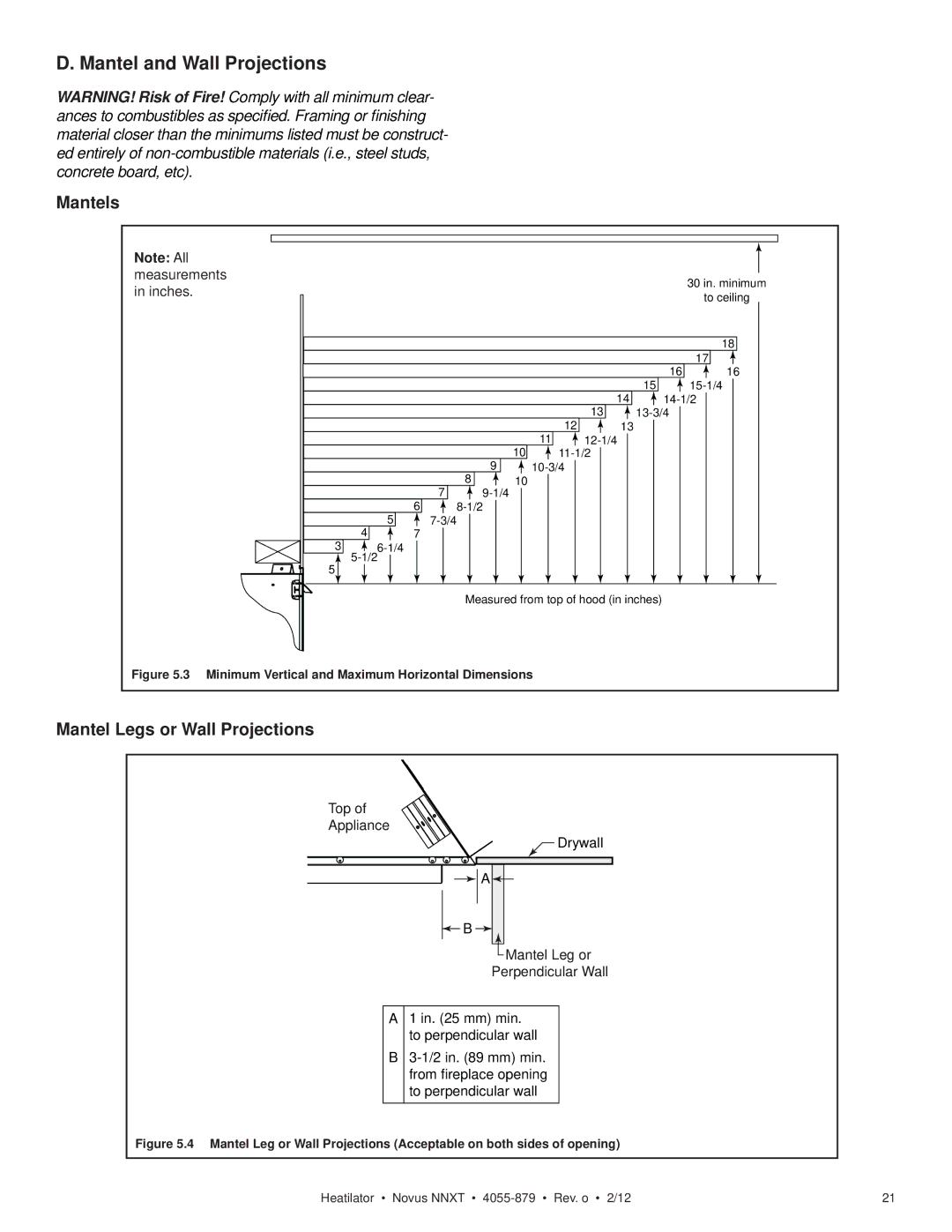
D. Mantel and Wall Projections
Mantels
Mantel Legs or Wall Projections
A. Vent Termination Minimum Clearances
6 Termination Locations
Horizontal
20 in
S min = # term caps x
Figure 6.3 Minimum Clearances for Termination
T max = 2/# term caps x S actual
Heatilator Novus NNXT 4055-879 Rev. o 2/12
A. Approved Pipe
7 Vent Information and Diagrams
B. Vent Table Key
C. Use of Elbows
1. Top Vent - Horizontal Termination
E. Vent Diagrams
V1 H1
One Elbow
H3 Installed Horizontally
1. Top Vent - Horizontal Termination - continued
Installed Vertically
Two 45 Elbows replacing One 90 Elbow
2. Top Vent - Vertical Termination
Installed Vertically
Install Top Vent Flue Visor - No Elbow Configura
1. Top Vent - Horizontal Termination - continued
Lift top refractory and hold in place
Remove the side refractory
Pull side refractory forward & out
Lower & twist pull out
Three Elbows
2. Top Vent - Vertical Termination - continued
12 ft 3.66 m min 60 ft 18.29 m max
Heatilator Novus NNXT 4055-879 Rev. o 2/12
Two Elbows
2. Top Vent - Vertical Termination - continued
12 ft 3.66 m min. 60 ft 18.29 m max
Heatilator Novus NNXT 4055-879 Rev. o 2/12
18 in. 457 mm max
3. Rear Vent - Horizontal Termination
No Elbow
One 45 Elbow
3. Rear Vent - Horizontal Termination - continued
V1 H1
Installed Horizontally
Two Elbows
One Elbow
4. Rear Vent - Vertical Termination
0 min 6 ft 1.83 m max 12 ft 3.66 m min 60 ft 18.29 m max
Two Elbows
Three Elbows
4. Rear Vent - Vertical Termination - continued
0 min 6 ft 1.83 m max 12 ft 3.66 m min
60 ft 18.29 m max. Maximum horizontal run is
A. Pipe Clearances to Combustibles
8 Vent Clearances and Framing
B. Wall Penetration Framing
Combustible Wall Penetration
C. Install the Ceiling Firestop
D. Install Attic Insulation Shield
Flat Ceiling Installation
Vaulted Ceiling Installation
A. Top Vent
9 Appliance Preparation
Wear protective gloves and safety glasses during installa
NOTICE Once appliance is set up for top or rear venting
B. Rear Vent
Discard the vent cap, remove and discard the insulation
it CANNOT be changed at a later time
WARNING! Risk of Fire! Prevent contact with
C. Secure and Level the Appliance
Sagging or loose insulation Insulation backing or plastic
Framing and other combustible materials
A. Assemble Vent Sections DVP Only
10 Install Vent Pipe
Attach Pipe to the Firebox Assembly
Assemble Pipe Sections
B. Assemble Vent Sections SLP Only
C. Assemble Slip Sections
Only outer pipes are sealed, sealing the inner flue is not required
E. Disassemble Vent Sections
D. Secure the Vent Sections
F. Install Decorative Ceiling Components SLP only
G. Install Metal Roof Flashing
H. Assemble and Install Storm Collar
CAULK
J. Install Decorative Wall Components SLP only
I. Install Vertical Termination Cap
K. Heat Shield Requirements for Horizontal Termination
Termination Cap
L. Install Horizontal Termination Cap
1-1/2 38 mm minimum overlap of flue telescoping section is required
Failure to maintain overlap may cause overheating and fire
A. HHT Shrouds
11 Shrouds
B. Field Constructed Shrouds
Open Top Shroud may be used with DVP-TV, DVP-TVHW, SLP-TVHW
Figure 11.2 Roofed Style Shroud Dimensions
Figure 11.2 Mailbox Style Shroud Dimensions
Mailbox Style Shroud may be used with DVP-TV, DVP-TVHW, SLP-TVHW
Roofed Style Shroud may be used with DVP-TV, DVP-TVHW, SLP-TVHW
A. Fuel Conversion
12 Gas Information
B. Gas Pressure
C. Gas Connection
B. Intellifire Plus Ignition System Wiring
A. Wiring Requirements
C. Optional Accessories Requirements
13 Electrical Information
Figure 13.1 RC200 Wiring Diagram
D. Electrical Service and Repair
F. Wall Switch Installation for Fan Optional
E. Junction Box Installation
Switch
Power
Installation Precautions
G. Remote Control Installation & Operations
Introduction
Determine Location
AUX200 Module Installation
Installation of Remote Control Housing
Fan Installation
RED LED
Programming the RC200 to the Control Module
Setting the Child Lock
Function Buttons
FAN CORD
Frequently Asked Questions/Troubleshooting
Power Outage
Manual Fireplace Shutoff
NOTICE Battery polarity must be correct or module damage will occur
A. Mantel and Wall Projections
14 Finishing
Figure 14.1 Minimum Vertical and Maximum Horizontal Dimensions
Mantels
B. Facing Material
B. Remove Screen Package Assembly
15 Appliance Setup
D. Removing Fixed Glass Assembly
A. Remove the Packaging
H. Accessories
G. Clean the Appliance
L. Assemble Logs
I. Place the Rockwool
M. Replacing Fixed Glass Assembly
N. Air Shutter Setting
Close Open
R. Install Control Heat Shield
Q. Install Hood
O. Remove Screen Protector
P. Unpackage the Hood & Floor Cover
S. Install Floor Cover
Bend to a 90 angle
Control Heat Shield in Place
T. Close the Screen Assembly
Open
Hang Screen on Shoulder Screws
A. Intellifire Plus Intermittent Ignition System
16 Troubleshooting
Symptom
Possible Cause
Intellifire Plus Intermittent Pilot Ignition System - continued
17 Reference Materials
A. Appliance Dimension Diagram
19-1/8 in 486 mm 11-5/8in 295 mm Gas Line Access
Alternative
124 mm
B. Vent Components Diagrams
10-1/2 in
267 mm
RF6M
B. Vent Components Diagrams continued
RF12M
Roof Flashing Multi-pak
9 in
B. Vent Components Diagrams continued
2-3/4 in
229 mm
15-1/8 in 384 mm 12 in. 305 mm
B. Vent Components Diagrams continued
8 in 203 mm Heat Shield
Effective
DVP-TRAP to DVP-HPC Side Filler Kit
B. Vent Components Diagrams continued
DVP-HRC-SS
DVP-HRC-ZC-SS
B. Vent Components Diagrams continued
203 mm
B. Vent Components Diagrams continued
101 mm
3-13/16 in
9 in
B. Vent Components Diagrams continued
12-1/2 in
2-3/4 in
C. Service Parts
Log Set Assembly
NNXT3933I, NNXT4236I
Part number list on following page
NNXT3933I, NNXT3933IL
C. Service Parts continued
Stocked
at Depot
C. Service Parts continued
NNXT4236I, NNXT4236IL
Stocked
at Depot
C. Service Parts
#16 Ignition Control Assembly
#15 Valve Assembly
NNXT3933I, NNXT4236I
LDS33/LDS46 Decorative Shroud
D. Optional Components
LDS-BV Decorative Shroud
TCG375 Terra Cotta Cap LDSCP-M Shroud Leg Multipack not shown
DO NOT DISCARD THIS MANUAL
E. Contact Information