48V | 12V |
|
|
|
|
|
| |
|
|
|
|
|
|
| ||
| 3.3V |
|
|
|
| Glacier | ||
|
|
|
|
|
|
| ||
12V |
|
|
|
|
|
| 12V (main) | |
5V |
|
|
|
|
| 5V (Standby) | ||
|
|
|
|
|
| |||
Total 8 modules mountable |
|
|
|
|
| FC - SW | ||
|
|
|
|
|
|
| ||
|
|
| Flash |
|
|
|
| |
|
| Five |
|
| UART |
|
| |
|
|
|
|
|
| Processor | ||
LED |
|
|
| I2C |
| |||
LAN | 82,546 GB | 41210 |
|
| CPLD | |||
64b 100MHz | FC 4.25 Gbs (Max) | Local Data Bus | ||||||
(GbE) | ||||||||
RJ45+(MAG) |
|
| Bridge | Con. | else | |||
ROM |
|
| ||||||
|
| 64b 6MHz (4Gbs) |
|
|
|
|
| |
PCIeX4 (Server blade | #0) |
|
|
|
|
| ||
PCIeX4 (Server blade | #1) |
|
|
|
|
| ||
PCIeX4 (Server blade | #2) |
|
|
|
|
| ||
PCIeX4 (Server blade | #3) |
|
|
|
|
| ||
PCIeX4 (Server blade | #4) |
|
|
|
|
| ||
PCIeX4 (Server blade | #5) |
|
|
|
|
| ||
PCIeX4 (Server blade | #6) |
|
|
|
|
| ||
PCIeX4 (Server blade | #7) |
|
|
|
|
| ||
|
|
|
| RS232C |
|
|
| |
|
|
|
| Connector |
|
|
| |
I2C |
| I2C |
|
|
|
|
| |
|
| Hub |
| I2C |
|
|
| |
|
|
|
|
|
|
| ||
|
|
|
| Reg. |
|
|
| |
SFP
SFP
SFP
SFP
RJ45
For management
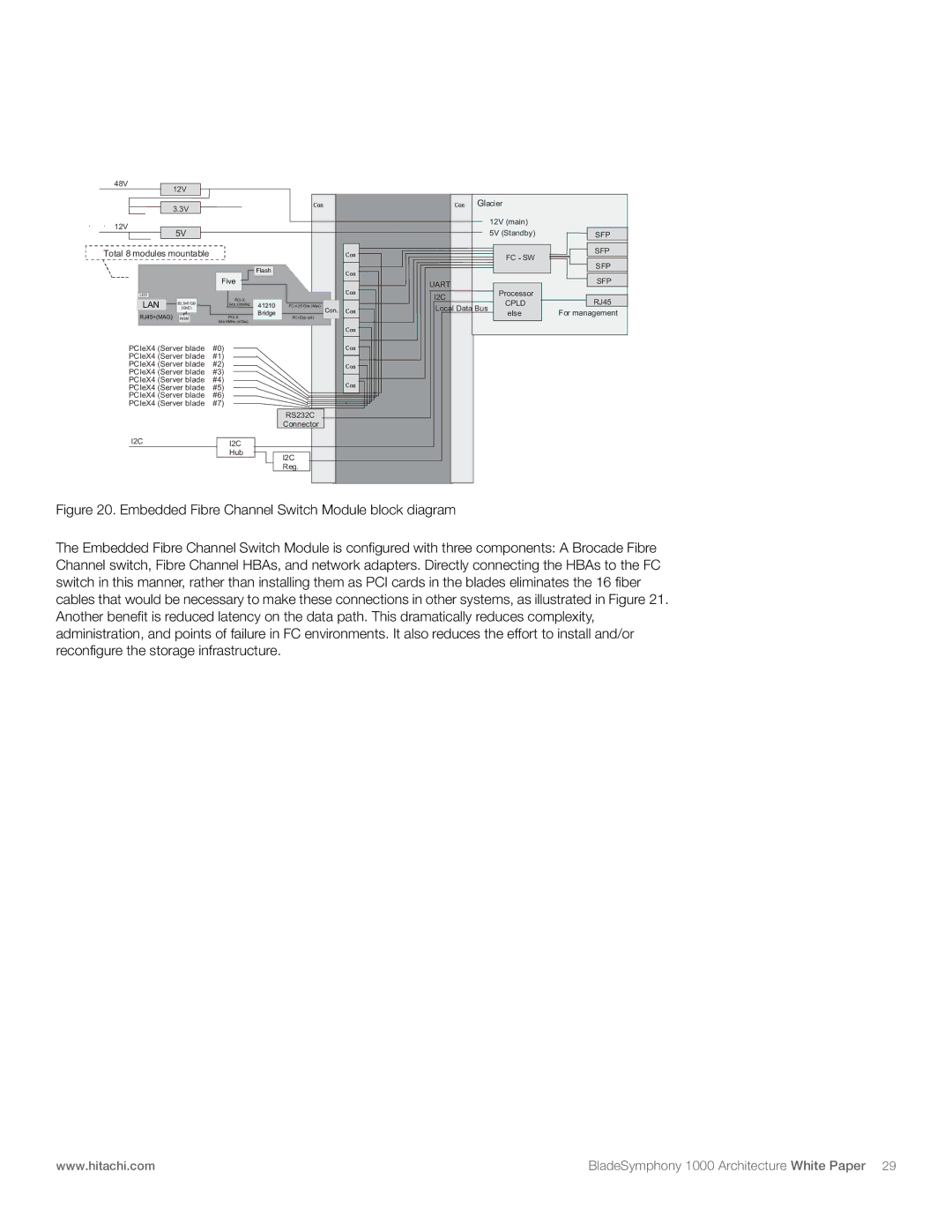
Figure 20. Embedded Fibre Channel Switch Module block diagram
The Embedded Fibre Channel Switch Module is configured with three components: A Brocade Fibre Channel switch, Fibre Channel HBAs, and network adapters. Directly connecting the HBAs to the FC switch in this manner, rather than installing them as PCI cards in the blades eliminates the 16 fiber cables that would be necessary to make these connections in other systems, as illustrated in Figure 21. Another benefit is reduced latency on the data path. This dramatically reduces complexity, administration, and points of failure in FC environments. It also reduces the effort to install and/or reconfigure the storage infrastructure.
www.hitachi.com | BladeSymphony 1000 Architecture White Paper 29 |