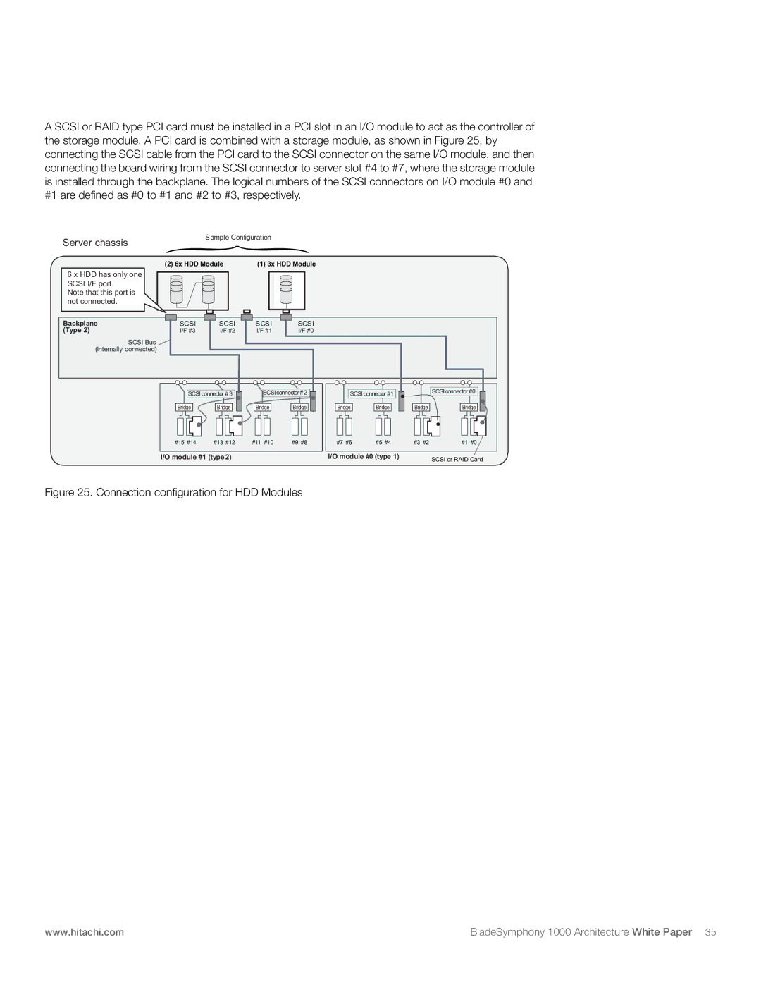
A SCSI or RAID type PCI card must be installed in a PCI slot in an I/O module to act as the controller of the storage module. A PCI card is combined with a storage module, as shown in Figure 25, by connecting the SCSI cable from the PCI card to the SCSI connector on the same I/O module, and then connecting the board wiring from the SCSI connector to server slot #4 to #7, where the storage module is installed through the backplane. The logical numbers of the SCSI connectors on I/O module #0 and #1 are defined as #0 to #1 and #2 to #3, respectively.
Server chassis
Sample Configuration {
(2) 6x HDD Module | (1) 3x HDD Module |
6x | SCSI i/f |
|
|
|
|
6 xHDD has only one |
|
|
|
| |
SCSI I/F port. |
|
|
|
| |
Note that this port is |
|
|
|
| |
not connected. |
|
|
|
| |
Backplane | SCSI | SCSI | SCSI | SCSI | |
(Type 2) |
| I/F #3 | I/F #2 | I/F #1 | I/F #0 |
| SCSI Bus |
|
|
|
|
| (Internally connected) |
|
|
|
|
SCSIconnector # 3 | SCSIconnector #2 | SCSI connector #1 |
| SCSI connector #0 | |||
Bridge | Bridge | Bridge | Bridge | Bridge | Bridge | Bridge | Bridge |
#15 #14 | #13 #12 | #11 #10 | #9 #8 | #7 #6 | #5 #4 | #3 #2 | #1 #0 |
I/O module #1 (type 2) |
|
| I/O module #0 (type 1) |
| SCSI or RAID Card | ||
Figure 25. Connection configuration for HDD Modules
www.hitachi.com | BladeSymphony 1000 Architecture White Paper 35 |
