SVP-LAN1: For management
(Not opened to user)
LAN connection
Power control connector of multiple chassis
1000Base-TSVP-LAN0: Exclusively for maintenance Serial I/F for on site service
MAINT1 Port
PWCTRL1 Port
GLAN0-3 Port SVP-LAN Port
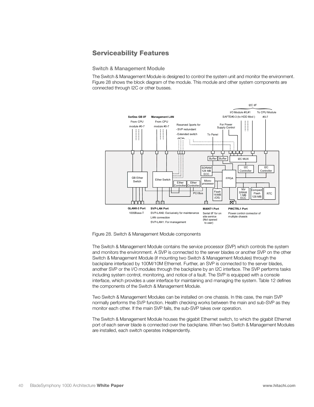
Figure 28. Switch & Management Module components
The Switch & Management Module contains the service processor (SVP) which controls the system and monitors the environment. A SVP is connected to the server blades or another SVP on the other Switch & Management Module (if mounting two Switch & Management Modules) through the backplane interfaced by 100M/10M Ethernet. Further, an SVP is connected to the server blades, another SVP or the I/O modules through the backplane by an I2C interface. The SVP performs tasks including system control, monitoring, and notice of a fault. The SVP is equipped with a console interface, which provides a user interface for maintaining and managing the system. Table 12 defines the components of the Switch & Management Module.
Two Switch & Management Modules can be installed on one chassis. In this case, the main SVP normally performs the SVP function. Health checking works between the main and sub-SVP as they monitor each other. If the main SVP fails, the sub-SVP takes over operation.
The Switch & Management Module houses the gigabit Ethernet switch, to which the gigabit Ethernet port of each server blade is connected over the backplane. When two Switch & Management Modules are installed, each switch operates independently.
Serviceability Features
Switch & Management Module
The Switch & Management Module is designed to control the system unit and monitor the environment. Figure 28 shows the block diagram of the module. This module and other system components are connected through I2C or other busses.
| | | I2C I/F | |
| | | { |
| | | I/O Module #0,#1 | To CPU Module |
SerDes GB I/F | Management LAN | | SAFTE#0-3 (to HDD Mod ) | #0-7 |
From CPU | From CPU | Reserved 3ports for | For Power | |
module #0-7 | module #0-7 | |
- SVP redundant | Supply Control | |
| | |
| | | |
| - Extended switch | | To Panel | | | | | |
| { | | | | | | | | |
| | | | Buffer | Buffer | I2C MUX | | | |
| | | SDRAM | | I2C | | | I2C |
| | | 128 MB | | Controller | Controller |
| | | | ECC | | | | | |
GB Ether | Ether Switch | | | Micro- | FPGA | | | | |
Switch | | | | | | | |
Ether | Ether | | | | | | |
| processor | | | | | |
| Controller | Controller | | | | | |
| | | | | | | |
| | | | Flash | NV- | Compact | |
| | PCI Bus | SRAM | | Flash | RTC |
| | 16MB | |
| | | | 1 MB | | 128 MB | |
| | | | (OS) | ECC | | |
| | | | | | |
40 BladeSymphony 1000 Architecture White Paper | www.hitachi.com |